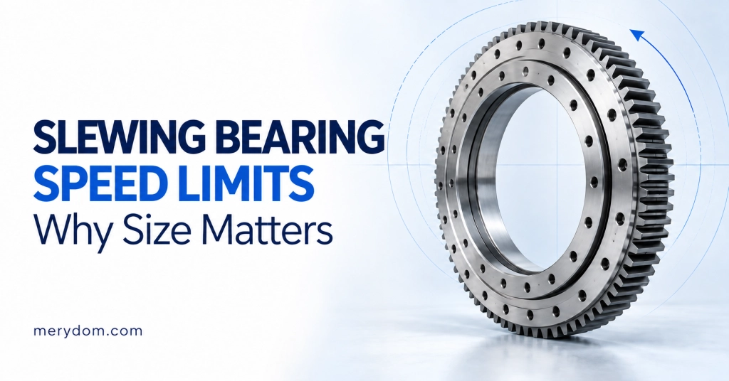
Every standard slewing bearing is one of four structures: single-row ball, double-row ball, crossed cylindrical roller, or three-row roller. The structures differ in how rolling elements meet raceways — and that single geometric choice decides load capacity, stiffness, speed limit, height, and price. This guide compares the four honestly, then walks the actual selection method: loads to equations to the static limiting diagram. It is the long-form companion to our standard models overview, where every structure's full dimension tables live.
The four structures in one view
Single-row four-point contact ball (011/012 · 013/014 · 010 · plus 06 light and 23 flange). One ball row, each ball touching its gothic-arch raceways at four points. The geometry carries axial, radial and moment loads in both directions from a single compact row — the reason it is the industry’s default: excavators, truck cranes, aerial platforms, turntables. Sturdy, cost-effective, the highest speed capability of the four (four-point contact generates less friction than roller line contact), and the shallowest section height.
Double-row ball (021/022 · 023/024 · 020). Two ball rows on separate raceways divide the duty — upper row takes main axial plus the moment’s compression side, lower row the lift-off side. Higher axial and moment capacity than a single row of the same diameter, bought with more height and weight. The pragmatic middle step when a load case outgrows single-row but three-row cost is not yet justified.
Single-row crossed cylindrical roller (111/112 · 113/114 · 110). Cylindrical rollers alternate at 90° in one raceway, line contact replacing point contact. The result is the stiffness specialist: highest running accuracy, suitable for preloaded zero-clearance arrangements, best vibration resistance. The trade: speed limits around 1.5 m/s tangential for continuous slewing (roller ends rub), versus up to 4 m/s for ball structures. Home ground: precision turntables, indexing tables, radar and antenna pedestals, machine tools.
Three-row roller (131/132 · 133/134 · 130). Three dedicated roller rows — main axial, reverse axial, radial — each in pure rolling on its own raceway. Diameter for diameter, the highest static capacity of any standard structure, at the cost of the tallest section, the greatest weight, and the strictest mounting-flatness demands. Home ground: crawler cranes, mobile harbour cranes, heavy deck machinery, ladle turrets.
Suitability at a glance (catalogue selection guide)
| Structure | Running accuracy | High speed | Heavy static loads | Vibration | Service life |
|---|---|---|---|---|---|
| Single-row ball | o | + | + | o | o |
| Double-row ball | o | o | + | o | o |
| Crossed roller | + | – | o | + | + |
| Three-row roller | o | – | + | + | + |
+ recommended · o suitable · – not recommended
The selection method: from machine to diagram
Step 1 — Derive the loads. From the machine’s geometry and masses, compute the resulting axial load and tilting moment for each governing working condition. For a boom machine: Fa = Qa + G1 + G2 + G3 (lifted load plus weight fractions), and Mt = Qa·L + Fr·Hr + G3·L3 − G1·L1 − G2·L2 (moments of load, radial force and each mass about the slewing centre). External radial loads Fr may be neglected while ≤ 5% of the axial load; above Fr/Fa = 0.6, the case needs engineering review. Critically, evaluate multiple conditions — on boom machines the light-load/maximum-radius case frequently governs, not the heaviest lift.
Step 2 — Apply the load factor. Multiply by the application factor fL before reading any diagram: 1.15 for turntables and handling workshops, 1.25 for sedimentation tanks, 1.33 for mini excavators, aerial platforms and service cranes, 1.5 for mobile cranes and concrete pumps, 2.0 for compactors and carrousels. The factor absorbs dynamics, shock and duty severity — skipping it is the classic self-deception of undersized selections.
Step 3 — Read the static limiting diagram. Plot each factored point (Far, Mtr) on the candidate bearing’s diagram. Two curves must both clear the point: the raceway capacity curve (permanent-deformation limit of the hardened raceway) and the bolting capacity curve (preload, joint separation and bolt limits, valid only for the specified bolt grade at full preload). All points inside both curves — the bearing qualifies. Any point above either curve — move up a size, a structure, or a bolt specification, whichever curve failed.
Step 4 — Check the envelope and the interface. Confirm Max OD (external gear: the tip diameter De exceeds D) or Min bore (internal gear: De is smaller than d) against the machine’s space; then bolt circles, hole counts, and height. Our model tables list the envelope values per model precisely because this check is skipped so often.
Choosing between neighbours: the honest tiebreakers
Single vs double row: if the factored point clears the single-row diagram with margin, stay single — lower height, lower cost, higher speed. Step up only when the diagram, not intuition, says so. Ball vs crossed roller: the question is never capacity, it is stiffness and positioning — if the application specifies deflection or repeatability, crossed roller; if it specifies speed, ball. Double row vs three row: at the boundary, mounting reality decides — a three-row bearing on a seat that cannot hold tenths-of-a-millimetre flatness performs worse than a double-row on the same seat. And across all four: when two structures both qualify, the cheaper, shorter, faster one wins; exotic structures are for cases that need them.
When a case sits near a curve, involves reversing moments, or carries duty the factors were not written for, send it through Load Case Review — MERYDOM engineering runs the check against your actual duty before quotation, and says plainly when a case belongs outside the catalogue. For machine-specific selection context, the industry application pages cover cranes, port machinery and platforms in depth.
FAQ
What are the main types of slewing bearings?
Four standard structures: single-row four-point contact ball, double-row ball, single-row crossed cylindrical roller, and three-row roller — differing in capacity, stiffness, speed and height.
When should I use a double-row instead of a single-row ball slewing bearing?
When the factored load point falls outside the single-row bearing’s static limiting curves at the required diameter — not before; double row costs height, weight and speed.
What is a crossed roller slewing bearing best for?
Applications specifying stiffness and positioning accuracy — preloaded, zero-clearance arrangements such as indexing tables and antenna pedestals — at limited slewing speeds.
What is the load factor fL?
An application multiplier (1.15–2.0) applied to computed loads before reading the static limiting diagram, absorbing dynamics and duty severity; mobile cranes use 1.5, aerial platforms 1.33.
Why are there two curves on a slewing bearing capacity diagram?
The solid raceway curve limits contact stress on the hardened raceway; the dotted bolting curve limits the bolted joint. A selection must clear both — on long-boom machines the bolt curve often governs.