
A rotary drilling rig may resemble an excavator with a mast, but its slewing joint carries a different combination of machine reactions. The ring connects the mast, rotary drive, Kelly bar, winches, counterweight and cab to the crawler undercarriage while the machine drills, extracts, lifts and repeatedly slews to discharge spoil. Accurate selection depends on the complete structural load path, not the headline torque of the rotary head.
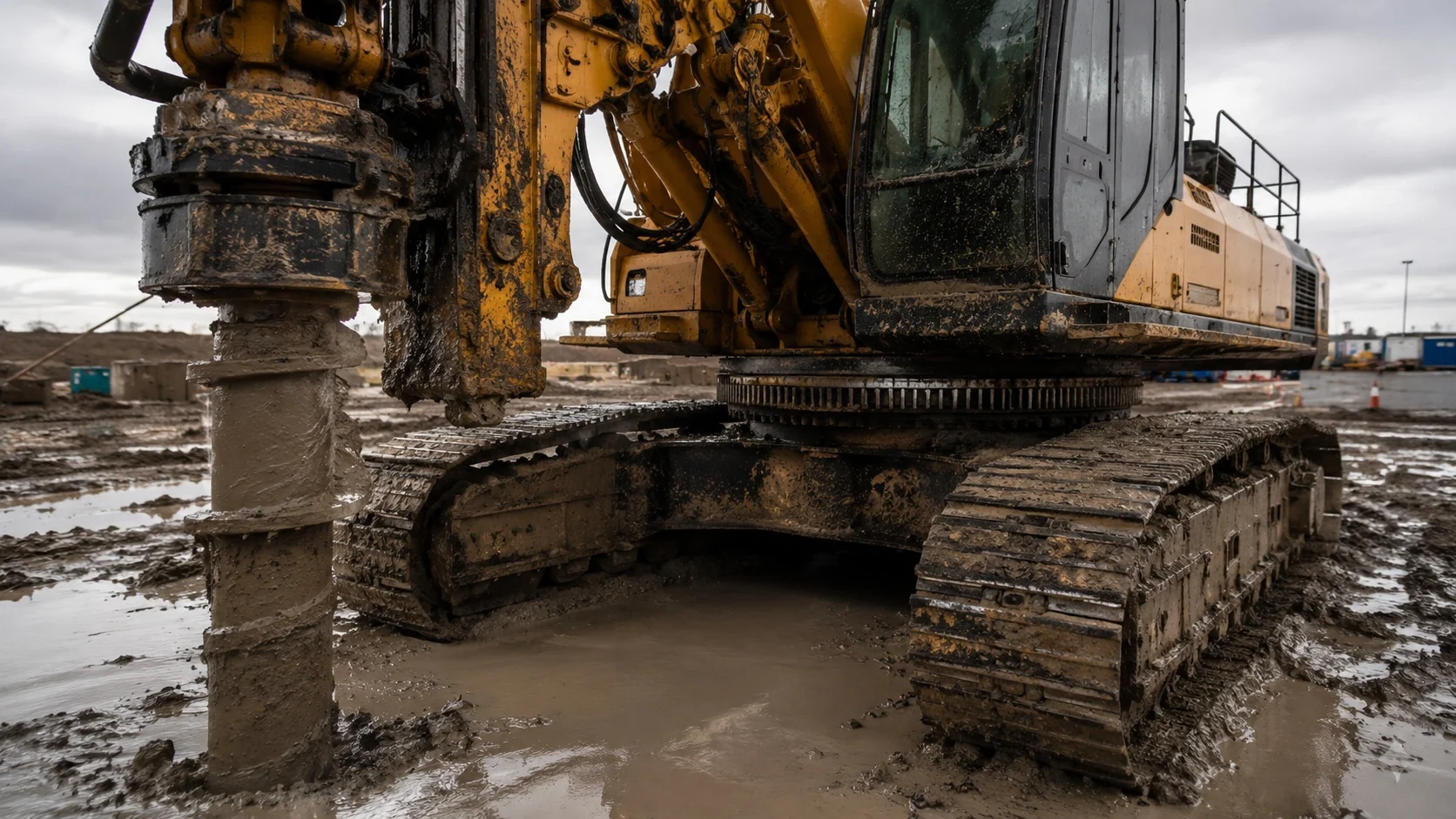
The drilling load case: crowd, pullback and torque reaction meet at one joint
Modern rotary rigs combine substantial rotary-head torque with crowd, extraction and casing forces. These published machine ratings do not transfer into the slewing bearing as one simple catalogue value. The equal and opposite structural reactions travel through the mast, mast foot, upper frame and crawler carrier, and their effect at the slewing joint depends on geometry, working radius, tool engagement, counterweight, crowd system and ground reaction.
The slewing bearing is not the rotary-head bearing. Its task is to connect and rotate the complete upper machine while carrying the axial load, radial load and tilting moment created by drilling and handling operations. Copying the rotary-head torque rating directly into a slewing-ring calculation is therefore not a valid selection method.
Use structural load cases
Review drilling, pullback, breakout, casing work, mast-folded transport and slewing with the tool or spoil suspended where these conditions apply.
Check the complete joint
Raceway capacity, mounting bolts, support stiffness, gearing and interface deformation must be verified together.
Rotary-head torque describes the drilling drive. Slewing-bearing loads must come from the machine structural model or an OEM-confirmed load-case sheet.
Short-angle slewing concentrates work in the same sectors
Kelly drilling creates a repetitive cycle: drill, extract the bucket or auger, slew through a limited angle, discharge spoil, slew back and repeat. A machine can perform many partial rotations without distributing work evenly around the full circumference. Raceway contacts, gear flanks and lubricant are therefore loaded most heavily in the same working sectors.
This duty makes circumferential consistency important. Raceway hardness and effective case depth should remain controlled around the complete ring, while the induction-hardening transition zone is marked and positioned according to the OEM installation drawing. Slew-drive backlash and gear alignment must also remain stable because every stop and reversal accelerates the complete upperstructure.
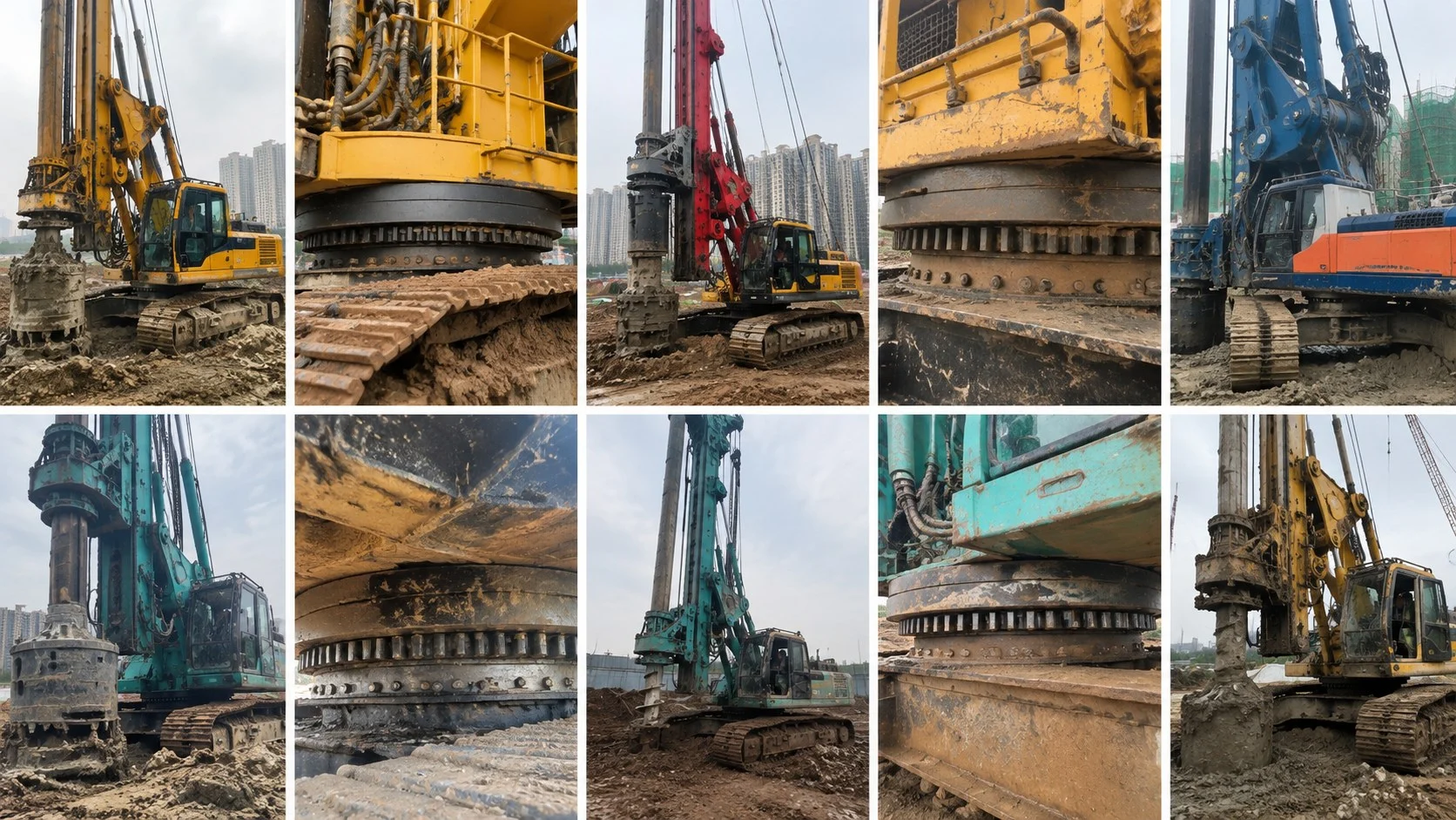
- Raceway consistencyVerify hardness, effective case depth and clearance to the agreed inspection plan, not only at one convenient angular position.
- Backlash controlSet gear backlash at the required reference position and recheck it after the bearing is bolted to the actual machine structure.
- Grease distributionLubricate while rotating through the available slew range so fresh grease reaches the working sectors and the seal purge can be inspected.
Internal gearing is common on crawler-mounted machines because the pinion and mesh can sit inside the centre frame. The 013/014 internal-gear single-row series is a starting point for some smaller and medium machines. Higher combined loads may move toward 023/024 double-row ball or 133/134 three-row roller structures. External gearing remains appropriate where the OEM drive layout requires it.
Crawler-frame stiffness: a good bearing cannot correct a distorted seat
Rotary drilling rigs work on temporary access roads, mats, compacted fill and ground whose support can change during the shift. The crawler centre frame may see torsion and local support variation while the tall mast magnifies small angular changes into large overturning effects.
The slewing ring assumes that the upper and lower mounting structures provide flat, sufficiently rigid interfaces. If either structure deflects beyond the verified allowance, rolling-element load concentrates on a short raceway arc, bolt loads become uneven and rotation torque rises. Tightening the mounting bolts harder cannot correct this geometry; it may pull the rings into the distorted seat and introduce damage from the first operating cycle.
For new machine design
Include centre-frame stiffness, upper-frame stiffness, bolt-joint behaviour and expected ground-related deformation in the machine calculation.
For replacement work
Inspect both seating faces for flatness, corrosion, fretting, burrs and local collapse around bolt holes before the new ring is installed.
Mud, bentonite and abrasive spoil make sealing part of the specification
Foundation equipment operates in soil, water, bentonite slurry, cement dust and spoil. Direct pressure washing at the bearing gap, damaged seal lips, blocked grease lines and inaccessible fittings are practical threats that should be addressed in the machine layout and maintenance plan.
- Seal arrangementDefine the lip seal, protective flinger or labyrinth arrangement required by the actual exposure and washdown method.
- Grease accessPlace fittings where they remain accessible after the mast, hoses and upperstructure are installed.
- Lubricant selectionUse the grease approved for the operating temperature, water exposure, contamination and duty cycle.
- Outward purgeFresh grease should reach the raceway and carry moisture or fine particles outward at the intended seal locations.
- Transport protectionProtect exposed gear teeth, machined faces and seals during transport, storage and site handling.
Water-emulsified grease, metallic particles, uneven purge or a sudden change in grease consumption should trigger inspection of the seals, lubrication lines, raceway condition and gear mesh rather than simply adding more grease.
The machine configuration matters more than the model name
One carrier model may be offered with Kelly drilling, continuous flight auger, full-displacement tools, double rotary systems, casing equipment, different crowd systems, mast extensions and counterweight packages. These options change machine mass, working radius, pull force and structural reaction. Two rigs with the same model badge can therefore require different bearing verification.
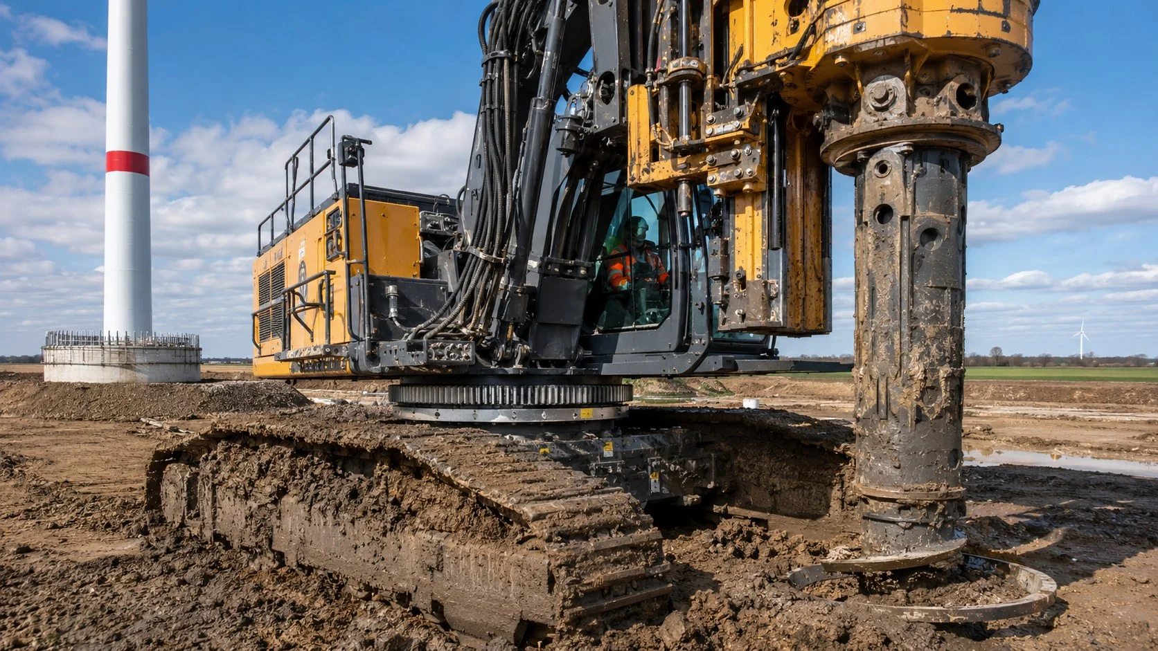
- Machine identityManufacturer, model, serial number and year.
- Working configurationMast, Kelly bar or auger, rotary head, crowd system, casing equipment and counterweight.
- Governing loadsAxial load, radial load and tilting moment at the slewing joint for drilling, pullback, breakout and slewing conditions, or the OEM load-case sheet.
- Bearing interfaceRing heights, pilot diameters, bolt circles, hole count and hole type.
- Gear dataInternal or external gear, module, tooth count, pressure angle, backlash target and hardening scope.
- Environment and maintenanceTemperature, slurry or dust exposure, sealing arrangement and lubrication system.
- DocumentationMaterial certificates, dimensional and clearance reports, hardness or case-depth records, NDT and traceability required by the project.
For European programmes, EN 16228 is a machine-level safety context for drilling and foundation equipment. Bearing records support the machine technical file, but the bearing itself does not certify the complete rig to that standard.
Replacing a rotary drilling rig slewing ring
Replacement projects often begin with a machine that still drills but shows increasing tilt, uneven rotation, abnormal slew-drive pressure or metallic grease. Identification requires more than the rig model because attachments and production revisions can change both loads and interfaces. Send the old-ring marking, upper and lower bolt-circle dimensions, ring heights, gear tooth count and module, plus clear photographs of the gear, seals and mounting faces through the RFQ channel.
The failure history is part of the specification. Early gear wear can indicate backlash error or mounting distortion; seal damage can indicate pressure washing or inaccessible grease points; bolt movement can indicate lost preload or a flexible seat. If the rig has been upgraded with a heavier rotary head, longer Kelly bar, casing system or additional counterweight, the replacement should be checked against the current configuration rather than only the original factory record.
MERYDOM publishes its factory, equipment capability, inspection capability, traceability system and supplier qualification data so foundation-equipment buyers can verify the machining, hardening, inspection and identification process before ordering.
Rotary Drilling Rigs slewing bearing FAQ
Which slewing bearing type is used on rotary drilling rigs?
Smaller and medium crawler rigs commonly use internal-gear single-row four-point contact ball bearings. Higher combined loads may require double-row ball or three-row roller structures. Final selection depends on the verified machine load cases, mounting stiffness, gear layout and duty cycle.
Is the rig slewing bearing the same as the rotary-head bearing?
No. The rotary head rotates the drilling tool. The slewing bearing connects the complete upperstructure to the crawler undercarriage and carries the combined structural reactions while allowing the upper machine to slew.
Why are internal gears common on crawler drilling rigs?
An internal gear can package the pinion and mesh inside the centre frame, improving protection from direct impact, mud and site contamination. External gearing remains valid where the OEM drive arrangement requires it.
Why is the drilling-rig configuration required for a replacement quote?
The same carrier may use different masts, rotary heads, Kelly bars, crowd systems, casing equipment and counterweights. These options change the loads and can also change the interface, so the model name alone is not enough.
What should be inspected when replacing the slewing ring?
Inspect the upper and lower seating faces, bolt holes, fasteners, gear alignment, lubrication lines and seals. Record the old-ring marking, interface dimensions and gear data, and investigate the original failure before fitting the replacement.
Send the current rig configuration and slewing-joint data
Include the machine identity, drilling configuration, verified load cases, mounting interface, gear data, environment, failure history and documentation requirements.