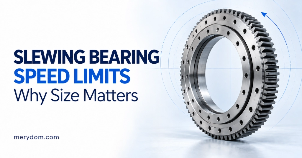
Learn how to select a crossed roller slewing bearing by load case, stiffness, clearance, mounting accuracy, gear arrangement and operating duty.

A crossed roller slewing bearing is often selected when a rotating structure needs more stiffness and positioning stability than a four-point contact ball bearing can provide, but the size, mass or cost of a three-row roller bearing is not justified. That description narrows the field, but it does not select a bearing. A reliable choice still depends on the complete load spectrum, permissible deflection, internal clearance or preload, mounting-structure accuracy, gear duty, lubrication and the bolted joint.
This guide presents a practical engineering workflow for choosing a single-row crossed cylindrical roller slewing bearing. It is intended for rotary tables, radar and antenna systems, manipulators, welding positioners, inspection equipment and other machinery where combined loads and controlled rotation share the same bearing position. For a broader comparison with ball and three-row roller structures, begin with our slewing bearing structure selection guide.
Why the crossed roller arrangement changes the selection
In a crossed roller bearing, adjacent cylindrical rollers are installed with their axes alternating by 90 degrees. The rollers therefore support load through line contact in two directions within one raceway. The arrangement can carry axial load, radial load and tilting moment simultaneously while maintaining a relatively compact cross-section.
The principal advantage is not simply “more capacity.” It is the relationship between load and deflection. Roller line contact, controlled raceway geometry and an appropriate clearance class can produce high rotational stiffness and running accuracy. Schaeffler describes crossed roller bearings as highly rigid, accurate units available with normal clearance, reduced clearance or preload. Those options matter because a bearing optimized for stiffness may have very different friction and thermal behavior from the same size supplied with clearance.
| Design requirement | Why crossed rollers may help | What must still be checked |
|---|---|---|
| High tilting stiffness | Roller line contact and opposing roller orientations resist overturning deformation | Moment-deflection curve, mounting-structure deformation and internal clearance |
| Combined axial, radial and moment load | One raceway supports multiple load directions | Every governing load combination, not three separate maximum values |
| Accurate indexing or tracking | Reduced clearance or preload can limit lost motion | Runout, gear backlash, drive compliance, friction torque and temperature |
| Compact bearing section | One crossed row can replace a multi-bearing arrangement | Bolt circles, gear envelope, support stiffness and service access |
Step 1: define the complete operating duty
Selection begins with load cases, not with an outside diameter. Record the axial force Fa, radial force Fr and tilting moment Mk acting at the bearing for each relevant machine condition. Include normal operation, maximum working radius, acceleration and braking, wind, emergency stop, transport, parked survival conditions and any reverse-load case. The maximum axial load, maximum radial load and maximum moment may occur at different times; combining three unrelated maxima can be unnecessarily conservative, while checking only the “heaviest” condition can miss the true governing case.
For each case, also record:
- percentage of operating time or expected cycles;
- rotation direction, speed and acceleration;
- continuous rotation or oscillation, including oscillation angle;
- shock, vibration and load reversals;
- required service life and acceptable maintenance interval;
- minimum and maximum operating temperature;
- dust, water, salt spray or chemical exposure.
Apply the appropriate service or application factor to working loads before comparing them with a static limiting-load diagram. The factor must reflect the machine category, duty severity and shock level; it should come from the bearing manufacturer’s validated method or an agreed project specification rather than a universal rule of thumb.
Step 2: screen raceway capacity and the bolted joint together
A slewing bearing is a system consisting of raceways, rolling elements, rings, bolts and the supporting structure. For that reason, a single axial or moment rating is not enough for final selection. Plot every factored load point on the candidate bearing’s applicable static limiting-load diagram. The point must remain within both the raceway limit and the bolting limit for the stated bolt grade, preload and mounting assumptions.
If the raceway curve governs, moving to a larger raceway diameter or a higher-capacity structure may be necessary. If the bolt curve governs, the correct response may involve the bolt circle, bolt size, preload or companion structure—not automatically a larger rolling element. Never use the raceway curve with a different bolt specification unless the bolted joint has been recalculated.
For applications with substantial accumulated rotation, calculate rolling-contact fatigue life from the manufacturer’s dynamic method and actual duty spectrum. Static safety and fatigue life answer different questions. A bearing can pass the maximum static load case yet fail to achieve the required life under repeated lower loads. Very small oscillation angles also deserve special review because lubricant may not redistribute normally across the loaded contact zone.
Step 3: convert “accuracy” into measurable requirements
Statements such as “high precision” or “zero play” are not sufficient procurement specifications. Define what the machine actually needs:
- maximum angular deflection under a stated tilting moment;
- axial and radial runout at defined reference surfaces;
- repeatability at the tool point or sensor;
- permissible starting and running torque;
- allowable gear backlash and reversal error;
- temperature range over which those values must be maintained.
The bearing is only one contributor to system accuracy. Ring deformation, bolt-joint slip, gearbox compliance, pinion backlash, frame distortion and control-system resolution can dominate the final result. Requesting an aggressively preloaded bearing cannot compensate for a flexible mounting flange.
Step 4: choose clearance or preload deliberately
Normal internal clearance is generally the most tolerant choice where smooth rotation, lower friction and thermal robustness matter more than maximum stiffness. Reduced clearance can improve positional stability without introducing the full sensitivity of a preloaded arrangement. Preload is appropriate when the application has a quantified stiffness or lost-motion requirement and when the supporting structure, lubrication and temperature control are capable of maintaining it.
Preload is not a free performance upgrade. Increasing preload usually raises friction torque and heat generation, reduces speed margin and makes the bearing more sensitive to mounting distortion and differential thermal expansion. The finished assembly—not merely the unmounted bearing—must retain the intended operating condition. For precision applications, request the manufacturer’s moment-deflection and friction-torque data for the proposed clearance class.
Step 5: select the gear arrangement and verify the drive load
MERYDOM standard crossed roller slewing bearings are available with external gear, internal gear or no gear:
| Series | Typical reason to choose it | Interface checks |
|---|---|---|
| 111/112 external gear | Accessible pinion, compact inner structure and straightforward inspection | Maximum outside envelope, guarding, pinion support and contamination |
| 113/114 internal gear | Protected gearing and a compact external envelope | Minimum bore, internal pinion space, lubrication and inspection access |
| 110 ungeared | Direct drive, friction drive or a separate transmission | Drive integration, torque transfer and ring clamping arrangement |
Calculate the pinion tangential force from drive torque and pitch diameter, then check gear-tooth capacity, pinion shaft and bearing loads, backlash, alignment, lubrication and the maximum start/stop torque. The tilting moment carried by the bearing and the torque transmitted by the gear are different load components; neither should be used as a substitute for the other.
Step 6: design the companion structure around the raceway
Large-diameter slewing bearings have relatively thin ring sections compared with their diameter. Their load distribution therefore depends strongly on the stiffness and flatness of the connected structure. Rothe Erde’s technical guidance emphasizes a rigid, torsion-resistant companion structure, mechanically processed contact surfaces and support located close to the rolling-element track.
Provide continuous, clean contact beneath both rings; avoid local high spots, unsupported sectors and abrupt stiffness changes. Specify permissible circumferential waviness and radial dish from the bearing supplier’s drawing or installation manual. Tighten bolts in the required cross sequence using a controlled method, then verify gear backlash and rotation over the full circumference. Welding or stress-relieving operations on the support should be completed before final machining.
This step is particularly important with reduced-clearance and preloaded bearings. A mounting surface that distorts one ring can create local roller overload, torque variation, heat and premature raceway damage even when the catalogue load calculation appears satisfactory.
Step 7: check speed, lubrication and environmental protection
Crossed roller slewing bearings are commonly used at low to moderate speeds, but there is no reliable universal speed limit. Permissible speed depends on raceway diameter, clearance or preload, cage or spacer design, lubricant, seals, temperature and load. Ask for a speed or friction review whenever the application rotates continuously, has frequent accelerations or must operate with preload.
Define the lubricant type, initial grease fill, relubrication quantity and interval together with the operating duty. Oscillating motion may repeatedly load the same short raceway sector, so grease distribution and relubrication positions need deliberate planning. For contaminated or outdoor machinery, check seal material, purge strategy and corrosion protection rather than assuming the standard sealing arrangement is sufficient.
A practical crossed roller selection workflow
- Build the load-case table: Fa, Fr, Mk, torque, speed, duration and direction for every operating and survival condition.
- Define performance: life, stiffness, runout, repeatability, friction torque and backlash.
- Choose a preliminary diameter and gear arrangement: external, internal or ungeared, based on the machine envelope and drive layout.
- Apply the agreed service factors: keep the original and factored values traceable.
- Check static capacity: confirm every point against both raceway and bolt curves.
- Check fatigue and oscillating duty: use the real load spectrum and movement pattern.
- Select clearance or preload: tie the choice to measurable stiffness and torque requirements.
- Verify the interface: mounting flatness, structural stiffness, bolt preload, gear mesh and lubrication access.
- Request engineering confirmation: especially for preload, reversing moment, shock, high speed or unusual temperatures.
Common mistakes that cause an undersized—or over-specified—bearing
- Selecting from outside diameter alone.
- Checking axial, radial and moment maxima separately instead of as simultaneous load combinations.
- Using a static load rating without checking the manufacturer’s limiting-load diagram.
- Specifying preload because it sounds precise, without defining allowable deflection or friction torque.
- Ignoring the bolt curve, support stiffness or mounting-surface tolerances.
- Using motor nominal torque instead of maximum start, brake or emergency torque for the gear check.
- Assuming a continuous-rotation lubrication plan will work for small-angle oscillation.
- Comparing suppliers by model number while overlooking different clearance, gear, bolt and accuracy assumptions.
What to send for a reliable quotation
A useful RFQ includes the load-case table, duty cycle, required life, rotation or oscillation pattern, target stiffness or runout, gear torque and ratio, mounting envelope, bolt limitations, operating temperature, environmental exposure and preferred lubrication strategy. Include drawings of the companion structure whenever stiffness or preload is critical.
Start with the external-gear, internal-gear or ungeared standard tables to establish the envelope. Then send MERYDOM your governing load cases for raceway, bolting and interface review before ordering.
FAQ
When should I choose a crossed roller slewing bearing?
Choose it when the application has combined loads and a quantified need for high rotational stiffness, running accuracy or controlled clearance in a compact single-bearing arrangement.
Is a crossed roller bearing always stronger than a four-point contact ball bearing?
No. Structure alone does not determine suitability. Compare the actual factored load points, limiting-load curves, life, stiffness, speed and mounting requirements for the candidate sizes.
Should a precision application always use preload?
No. Preload can improve stiffness and reduce lost motion, but it also raises friction and sensitivity to heat and mounting distortion. Use it only when the performance requirement and complete assembly justify it.
Can one load rating be used to select a slewing bearing?
Not for final selection. Combined axial load, radial load and tilting moment must be checked together, and both the raceway and bolted-joint limits must be satisfied.
What mounting information is most important?
Companion-structure stiffness, surface flatness, bolt size and preload, support location, gear alignment and the allowable deformation under working load are all essential.