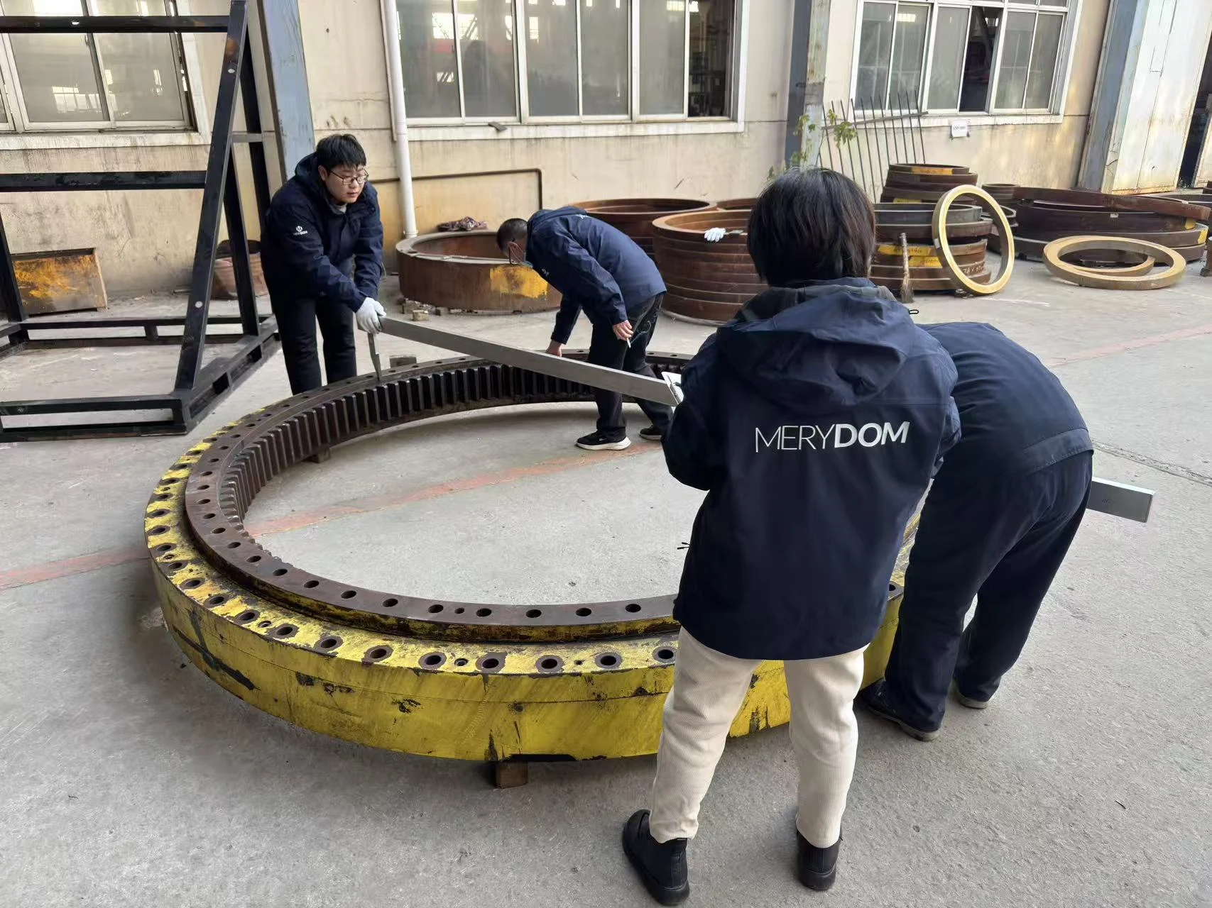
Diagnose slewing bearing gear pitting, abrasive wear, deformation and tooth breakage through contact patterns, torque history, lubricant and hardness evidence.
Gear damage on a slewing bearing often develops at the intersection of drive torque, pinion alignment, ring deformation and lubrication. Pitting, polished flanks, scoring and broken teeth are different symptoms and should not be grouped under the single label of poor gear quality.
The investigation must preserve tooth position and contact evidence around the circumference. Because the gear ring is also part of the bearing structure, mounting and bolt conditions can change mesh alignment after the pinion was correctly set during assembly.
Classify the visible damage
Pitting appears as small surface cavities and can progress when contact stress repeatedly exceeds the available surface strength. Abrasive wear produces scratches and material loss associated with hard particles. Adhesive scoring or smearing points to sliding contact, heat or lubricant-film failure. Plastic deformation changes the tooth profile without immediate fracture, while a broken tooth requires review of bending overload, cracks and prior damage.
Photograph the drive and coast flanks, root, tip and fracture surface before cleaning. Number teeth relative to the bearing marking and record whether damage is local or repeated around the ring. A short damaged sector may align with a tight backlash region, flexible structure or a frequently parked load position.
Review backlash and contact pattern around the circle
Backlash must accommodate manufacturing variation, thermal change, deflection and lubrication while preventing tooth interference. Measure it at the approved points and identify the tightest sector. Ring distortion after bolt tightening can make a mesh acceptable in one position and tight in another.
Use marking compound or another approved method to inspect contact position across the tooth face. Edge contact can indicate pinion misalignment, shaft deflection or nonparallel mounting. A narrow or shifting pattern concentrates stress and can initiate pitting even when module and tooth count match the drawing.
Reconstruct the real torque spectrum
Check maximum motor, gearbox and brake torque at the pinion, including start, stop, emergency and wind cases. Control-system limits, shock from clearance take-up and rapid reversal can create peaks above nominal operating torque. A jammed mechanism or external impact may leave a one-time overload signature.
Compare the calculated tangential force with tooth-root and contact capacity using the actual material, face width, heat treatment and load distribution. Do not use the bearing tilting moment as gear torque. The internal versus external gear guide describes the separate arrangement checks.
Use lubricant and hardness evidence correctly
Inspect lubricant coverage over the full circumference, not only near the service opening. Hard, dry or contaminated lubricant can prevent a protective film. Metal particles, cargo dust, sand or water support different mechanisms. Verify the product, application method and interval against the lubrication plan.
Review gear material, hardness pattern, effective depth where specified and transition-zone location. Hardness measurements must be taken at documented positions with a suitable method. A compliant certificate is supporting evidence, not proof that alignment, torque and lubrication were correct in service.
- Preserve tooth numbering, orientation and as-found photographs.
- Measure backlash and contact pattern at multiple positions.
- Collect lubricant and debris samples before cleaning.
- Review pinion bearings, shaft deflection and gearbox mounting.
- Check torque events, brake settings and control logs.
Turn the findings into corrective action
Corrective action may involve backlash setting, pinion alignment, lubricant delivery, contamination protection, torque limiting, support stiffness or a revised gear specification. Replace mating pinions when their damaged profile would overload a new ring. Confirm the full circumference after final installation and preserve a baseline contact record for future inspection.
FAQ
Why does only one gear sector fail?
Local backlash, alignment, support stiffness, parking position or contamination can concentrate load in one sector.
Does a broken tooth always mean low hardness?
No. Shock torque, fatigue cracks, alignment, root geometry and prior pitting can also cause breakage.
Should the old pinion be reused with a new gear ring?
Only after profile, wear, alignment and compatibility are approved. A damaged pinion can quickly harm the replacement ring.
Engineering references
For a drawing-based review, send MERYDOM the application, load cases, dimensions and required documentation. Final selection and service instructions must follow the approved drawing and equipment manufacturer requirements.