
A GOTTWALD PMA100216 port crane slewing bearing arrived with sticking, abnormal noise and increased clearance. Inspection and magnetic particle testing showed why repair had to stop.
A heavy-duty three-row roller slewing bearing from a GOTTWALD PMA100216 crane operating at Bangladesh’s largest port was shipped to MERYDOM’s factory in China after the crane developed intermittent sticking, increased bearing clearance and abnormal noise during slewing.
The machine belongs to the continuous-duty equipment group covered in MERYDOM’s slewing bearings for port machinery application guide, including portal cranes, mobile harbour cranes, grab unloaders and other ship-handling equipment.
The customer asked us to answer two separate questions:
- Could the original bearing be repaired safely?
- Could MERYDOM manufacture a new replacement bearing if repair was not viable?
This case shows why a repair decision cannot be based on visible surface damage alone. After dimensional inspection, disassembly, cleaning, controlled machining and magnetic particle testing, we found that the damage extended into the load-carrying ring material. Continuing the repair would have created an unacceptable technical and operational risk, so MERYDOM recommended stopping the repair and proceeding with replacement engineering.

Reported symptoms: sticking, clearance growth and abnormal noise
The three reported symptoms were consistent with advanced internal damage, although they did not identify a single root cause by themselves.
- Intermittent sticking can occur when damaged raceway geometry, displaced metal, large wear particles or distressed rolling elements disrupt smooth roller motion.
- Increased clearance can result from loss of raceway material, wear of rolling elements or permanent deformation in the loaded contact zones.
- Abnormal noise can be produced when rollers pass over spalled areas, cracks, indentations or trapped metallic debris.
Once these symptoms appear together on a heavy port crane, continued operation should not be treated as a harmless nuisance. Progressive material loss can change internal load distribution, concentrate load onto fewer rollers and accelerate secondary damage.
Step 1: Incoming inspection and dimensional verification
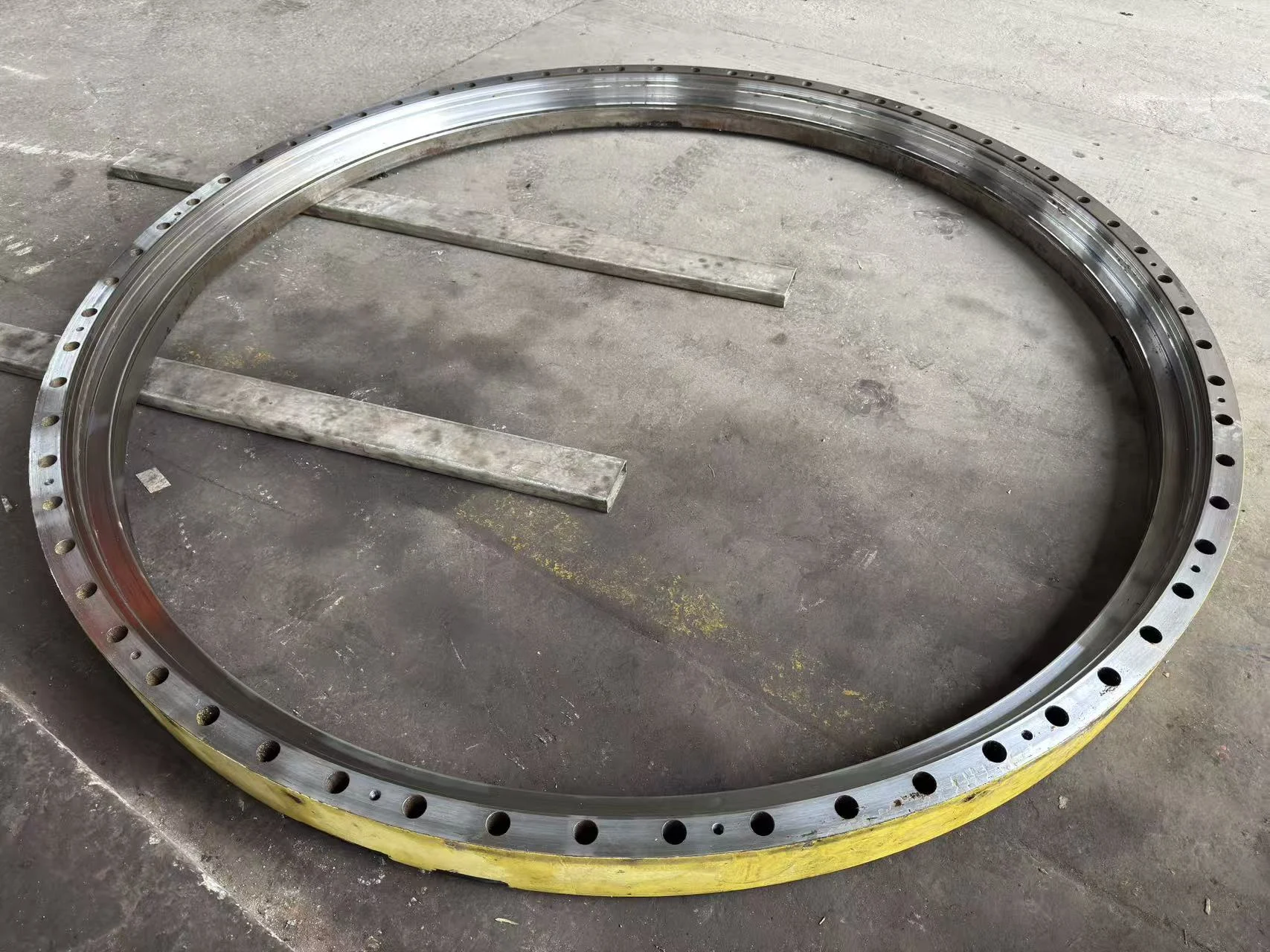
Before dismantling, the MERYDOM team recorded the bearing’s external configuration and checked its principal dimensions. Large-diameter bearing identification should never rely only on an old nameplate or a nominal outside diameter. Ring heights, pilot diameters, mounting-hole patterns, gear data, raceway arrangement and interface dimensions must be reviewed together.
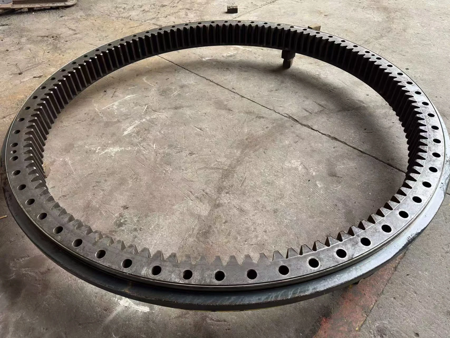
The measured geometry was broadly consistent with MERYDOM standard reference model 133.50.3150, an internal-gear, three-row roller slewing bearing.
The catalogue reference has a nominal envelope outside diameter of 3,432 mm, an envelope bore of 2,768 mm and an overall height of 270 mm. These similarities made 133.50.3150 a useful starting point for replacement engineering, but they did not establish automatic interchangeability.
A replacement for an existing crane must still be confirmed against the original bearing drawing and the actual machine interfaces, including:
- all ring and pilot diameters;
- total and individual ring heights;
- mounting-hole quantity, pitch circles, diameters and thread requirements;
- internal gear module, tooth count, profile shift, pressure angle and backlash requirements;
- axial, radial and tilting-moment load cases;
- operating duty, shock factors and expected service life;
- required internal clearances;
- lubrication, sealing and corrosion-protection arrangements;
- material, raceway hardness and effective hardened depth;
- inspection, traceability and certification requirements.
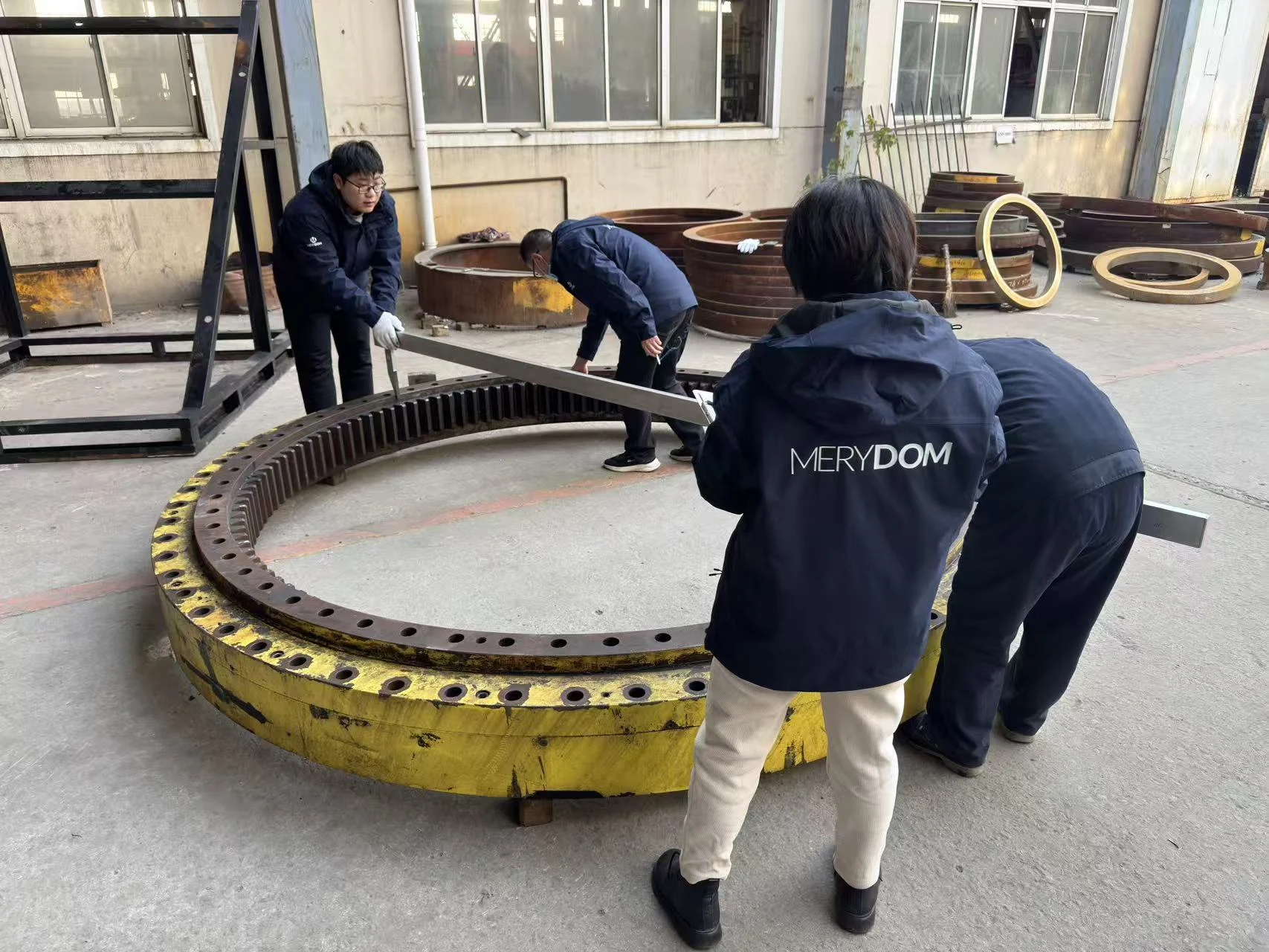
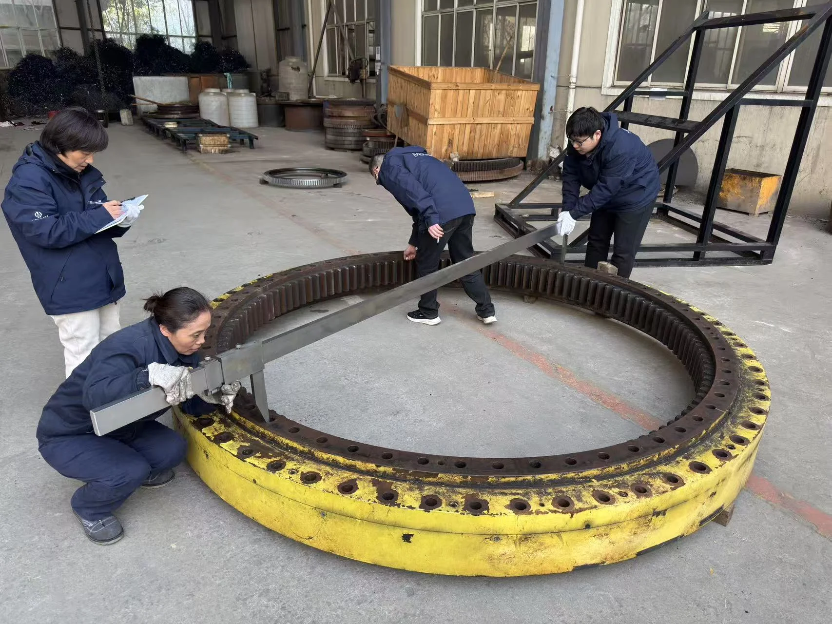
Video: Incoming bearing measurement
Watch the MERYDOM team verify the large bearing and its interface dimensions before dismantling.
Step 2: Disassembly and as-found condition
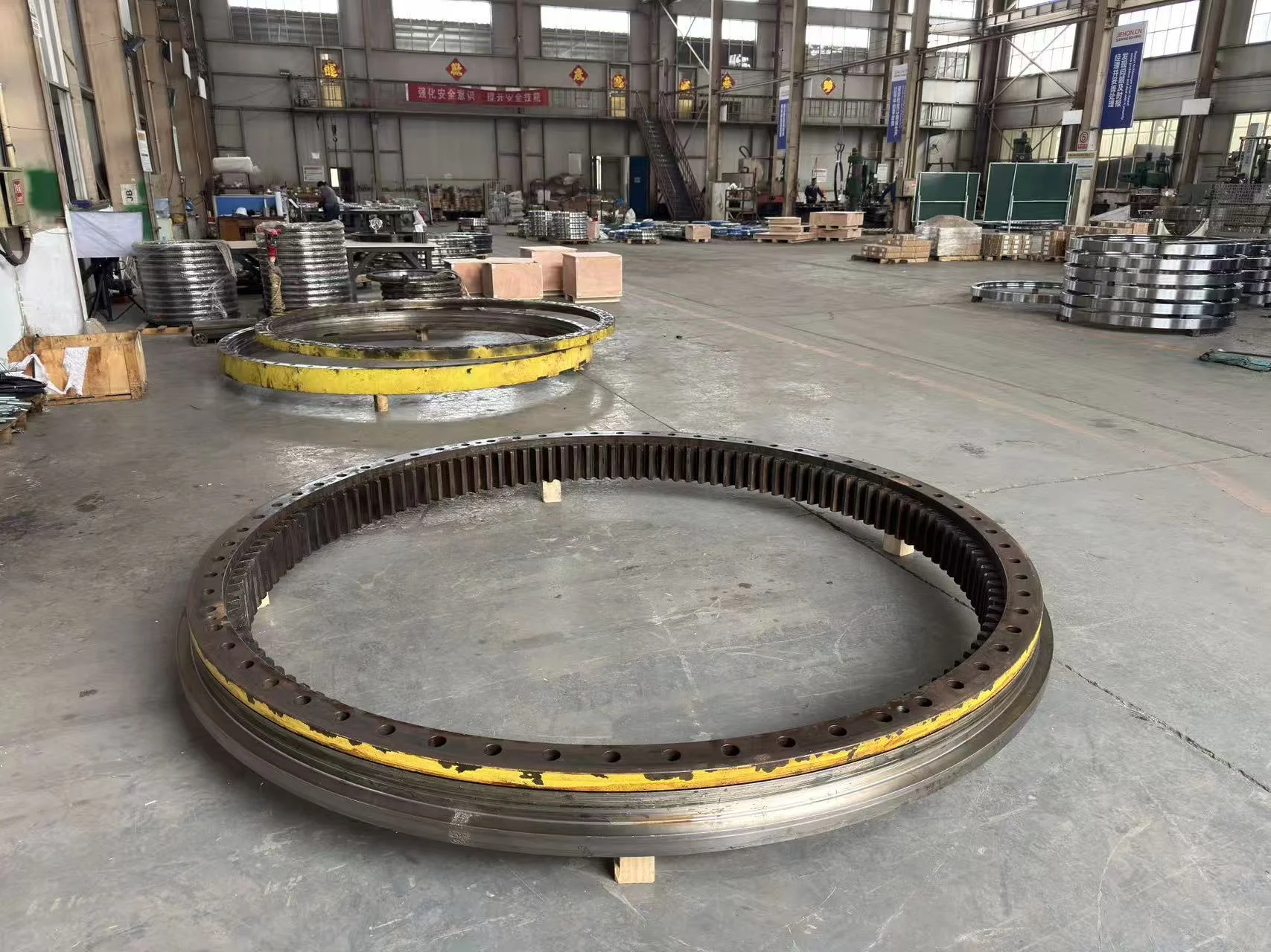
The bearing was opened and the accumulated grease, sludge and loose debris were removed so that the three-ring construction and raceway surfaces could be examined.
The overall inspection showed severe damage on the lower and middle ring raceways. The affected surfaces were not limited to light polishing or isolated shallow marks. The photographs show extensive spalling, scoring, smearing, local plastic deformation and macroscopic loss or displacement of raceway material.
These findings explained the reported operating symptoms:
- missing and displaced material increased internal clearance;
- distorted raceway geometry interfered with smooth rolling;
- loose metallic debris could be repeatedly overrolled;
- heavily damaged sectors produced impact and noise as load passed through them.
At this stage, a conventional light refurbishment—cleaning, polishing, replacing rollers and seals, and reassembling—was clearly insufficient.
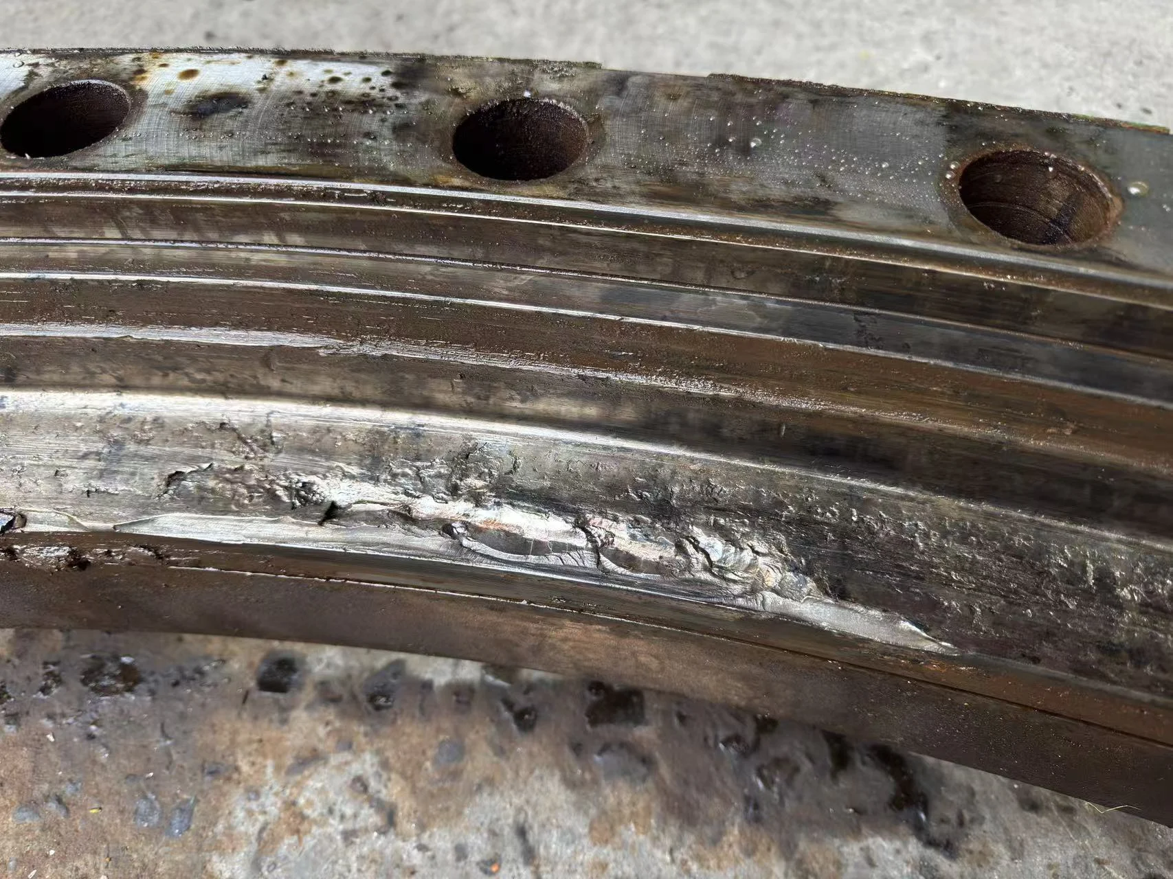
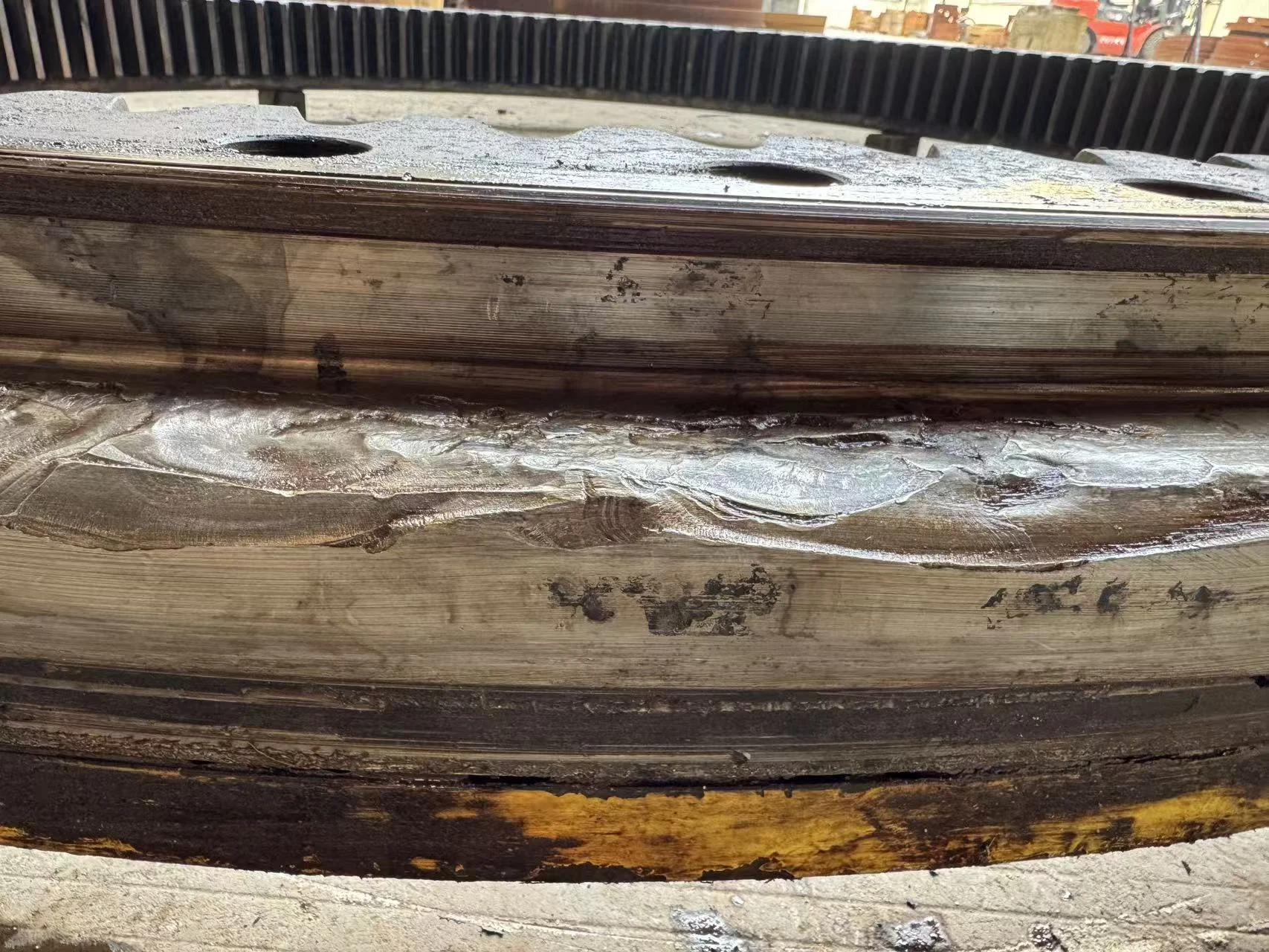
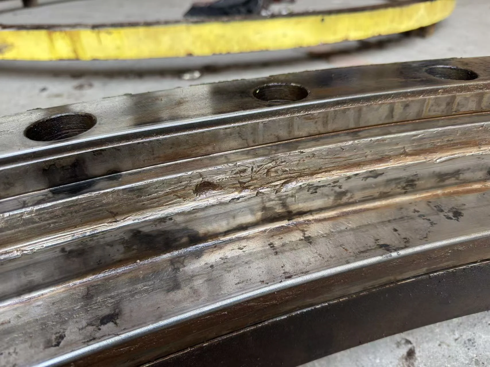
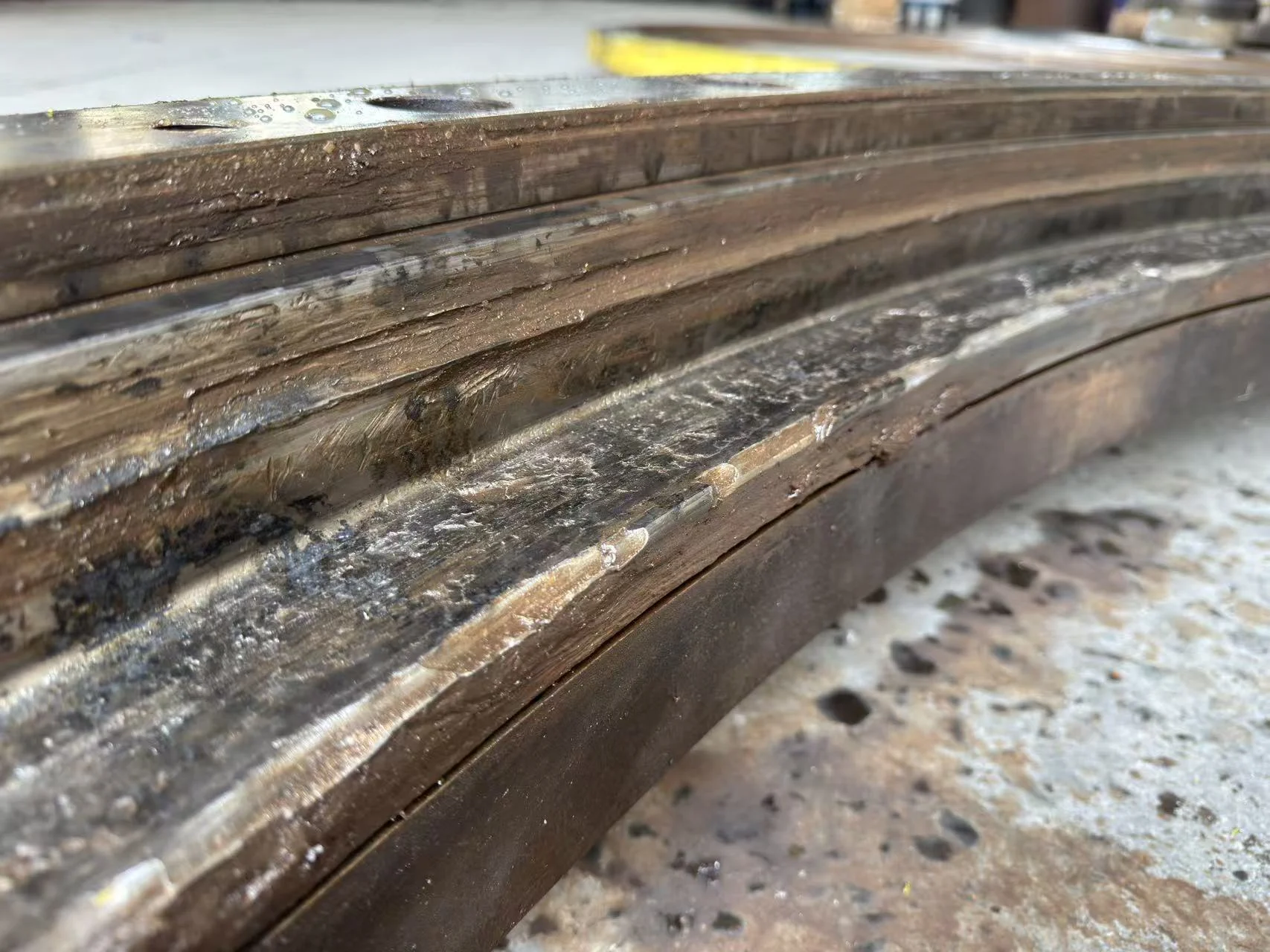
What can normally cause this type of raceway destruction?
The photographs document the final damage state, but they do not by themselves prove one initiating cause. A defensible root-cause investigation would also need operating hours, load history, lubrication records, seal condition, grease analysis, mounting-flatness data, bolt-preload records and the location of each damaged sector relative to the crane structure.
In heavy port-crane service, several mechanisms can initiate or accelerate this type of damage.
Port machinery deserves application-specific review because repeated loaded slews, short reversing arcs, abrasive cargo dust, coastal moisture and berth-downtime pressure act on the bearing as one operating system. The Port Machinery application guide explains how duty spectrum, support stiffness, gearing, automatic lubrication, sealing and planned replacement should be considered together.
1. Inadequate or degraded lubrication
A three-row roller bearing operates under high contact stress. If the lubricant film becomes insufficient, surface asperities contact directly, friction and temperature rise, and the raceway can develop smearing, scoring and surface-initiated fatigue.
Possible contributors include blocked lubrication lines, insufficient grease quantity, unsuitable grease, excessive relubrication intervals, grease aging or failure to rotate the bearing adequately during relubrication. Port cranes frequently slew through limited working arcs, so grease distribution around the full circumference deserves particular attention.
2. Water, salt and solid contamination
Port environments combine humidity, airborne salt, rain, dust and cargo contamination. Damaged seals or ineffective grease purging can allow water and abrasive particles to enter the raceway system.
Water can degrade grease and create corrosion pits. Hard particles can indent or scratch rolling surfaces. Both mechanisms create local stress raisers from which microcracks and spalling can develop. Once spalled metal circulates inside the bearing, the bearing begins generating its own abrasive contamination.
3. Shock loading or repeated overload
Grab impacts, sudden braking, emergency stops, off-design lifting events, ship movement and dynamic load amplification can produce contact stresses beyond the intended duty spectrum. A single severe event may create permanent deformation or subsurface damage; repeated overload can accelerate rolling-contact fatigue.
The correct assessment therefore requires the actual axial force, radial force and tilting moment—not crane capacity alone.
4. Mounting distortion and uneven bolt preload
A large slewing bearing depends on the stiffness and flatness of its supporting structures. Local high spots, a flexible pedestal, weld distortion, corrosion at the mounting interface or uneven bolt preload can deform the bearing rings.
The resulting edge loading or circumferential load concentration forces a smaller group of rollers to carry a disproportionate share of the load. Severe local damage can therefore occur even when the calculated global load appears acceptable.
5. Progressive clearance growth and continued operation
Initial wear changes internal geometry and load sharing. As clearance increases, rollers can experience greater impact, skew or sliding. Spalled fragments are then overrolled, producing further indentations and surface distress. This creates a self-accelerating sequence:
surface distress → microcracking → spalling → debris generation → clearance growth → impact and load concentration → larger spalls and deeper damage
6. Rolling-contact fatigue
All rolling bearings accumulate fatigue cycles. Subsurface cracks may initiate under repeated contact stress and eventually propagate to the surface. Lubrication failure, contamination, overload and distortion can shorten that process dramatically. In an advanced failure, several mechanisms may be present at the same time, and the earliest initiating evidence may already have been destroyed by secondary damage.
For a broader diagnostic framework, see Why Slewing Bearing Raceways Spall: Symptoms, Causes and Evidence.
Step 3: Controlled machining to expose the underlying material
The customer still wanted to determine whether a technically defensible repair route remained. MERYDOM therefore developed a staged assessment plan rather than promising a repair in advance.
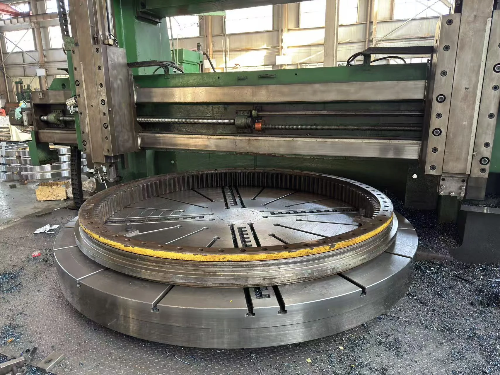
The ring was mounted on a vertical CNC machine, and the remaining damaged raceway layer was removed in a controlled operation. This step served two purposes:
- remove loose, heavily deformed and residual hardened material that could obscure inspection; and
- expose the underlying ring material for non-destructive testing.
Machining a raceway does not by itself make a bearing repairable. After material removal, the ring must still have sufficient section, sound substrate, recoverable geometry and a qualified route for rebuilding the raceway and restoring the required hardness profile.
Step 4: Magnetic particle testing changed the decision
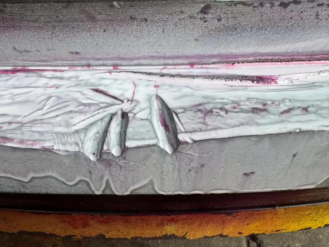
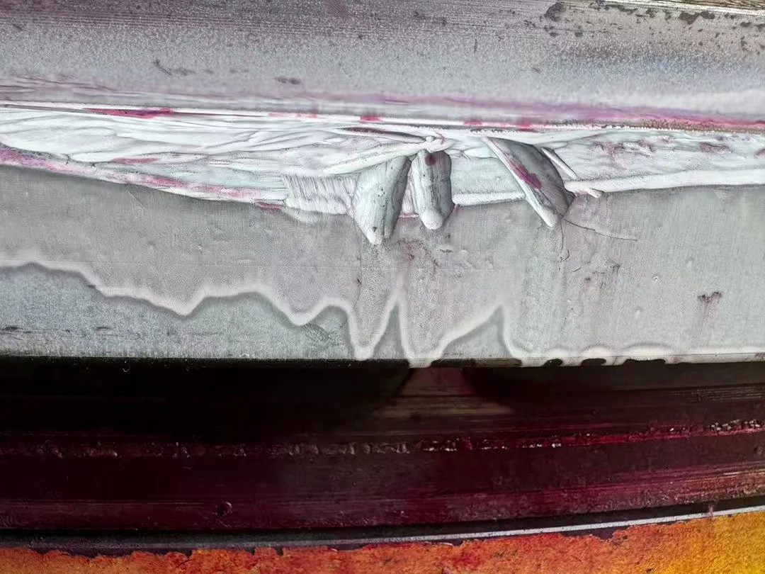
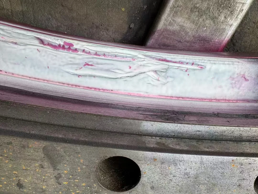
After machining, magnetic particle testing was performed on the exposed ferromagnetic ring surfaces. Magnetic particle inspection is used to reveal surface-breaking and near-surface discontinuities that may be difficult to distinguish by normal visual inspection.
The test produced pronounced linear indications in and around the damaged raceway zones. The pattern demonstrated that the problem was not merely superficial scoring or a removable damaged skin. Discontinuities remained in the underlying load-carrying material after the distressed raceway layer had been removed.
Video: Magnetic particle inspection
Watch the exposed raceway substrate being checked for crack indications after controlled machining.
Why MERYDOM rejected the bearing for repair
Repairability is not determined by whether damaged metal can physically be removed or filled. The repaired bearing must have a traceable engineering route to restore geometry, material integrity, raceway hardness, effective hardened depth, internal clearance and load-carrying capacity.
In this case, the combination of extensive raceway destruction and magnetic particle indications in the substrate created several unacceptable uncertainties:
- the full depth and circumferential extent of cracking could not be treated as a superficial defect;
- further material removal would reduce the ring section and change raceway geometry;
- local welding or build-up could introduce heat-affected zones, residual stress, distortion and new metallurgical discontinuities;
- a repaired area could not be assumed to recover the original rolling-contact fatigue performance;
- failure of a safety-critical crane slewing bearing could endanger personnel, equipment and port operations.
MERYDOM therefore informed the customer that the original bearing was not a safe candidate for continued refurbishment or further service. The repair plan was stopped, and replacement engineering became the appropriate path.
This decision meant giving up a substantial repair order. However, a large order does not justify lowering the acceptance criteria for a safety-critical component. A repair recommendation must follow inspection evidence, not commercial pressure.
Replacement engineering: use 133.50.3150 as a reference, not an assumption
Because the measured dimensions were close to MERYDOM standard model 133.50.3150, this model provides an efficient starting point for a new three-row roller, internal-gear replacement.
The final bearing should nevertheless be engineered from verified interface measurements, gear inspection, the original drawing where available, and the crane’s actual load and duty data. Particular attention should be given to:
- the loaded raceway orientation and load spectrum;
- support flatness and structural stiffness;
- bolt condition and preload procedure;
- lubrication delivery to every raceway;
- seal protection for the marine environment;
- baseline axial/tilting clearance measurements;
- inspection documentation for material, heat treatment, gearing and final assembly.
Replacing the bearing without correcting an initiating system problem can reproduce the same failure. The new-bearing project should therefore include both component design verification and a review of installation and maintenance controls.
Practical lessons from this case
- Sticking, rising clearance and abnormal noise together require prompt investigation.
- Visible spalling is a failure mode, not a complete root-cause conclusion.
- Dimensional similarity is useful for screening but does not prove interchangeability.
- Cleaning and machining must be followed by qualified inspection before repair is approved.
- Magnetic particle indications in the load-carrying substrate can change a repair project into a replacement project.
- A safe rejection is a successful engineering outcome when the evidence cannot support continued service.
- The replacement bearing and the surrounding crane system must be reviewed together.
Need a repairability or replacement review?
For a large slewing bearing assessment, provide the available bearing drawing, machine model, principal dimensions, gear data, operating symptoms, load information, clearance history, maintenance records and clear photographs.
MERYDOM can review the evidence, compare the bearing with standard references such as 133.50.3150, and define the information required for a repairability decision or new replacement design.
Review slewing bearing engineering for port machinery
Send the case details for engineering review
Although this case came from a port crane, the same inspection evidence is relevant to deck and barge equipment exposed to salt spray. Buyers specifying marine crane slewing bearings should treat coating breakdown, seal condition, water ingress and grease-purge performance as part of the failure investigation and replacement specification.