
Compare individual spacers, continuous cages and segmented cages in slewing bearings, with practical checks for materials, residual gap, torque, lubrication and validation.
In this guide: spacers, cages, materials and selection
Two slewing bearings can have similar outside dimensions, ring materials, raceway hardness and nominal load ratings, yet use very different rolling-element separation systems. One may use individual spacers between adjacent balls; another may use a continuous cage; a third may use a segmented cage.
The choice should not be reduced to the idea that one design is "more advanced" than another.
The real engineering question is:
Which separation architecture can control the rolling elements reliably under the actual load, motion, deformation, lubrication, temperature and duty-cycle conditions of the application?
For many low-speed, intermittent slewing applications, individual spacers are a practical and proven solution. For continuous rotation, higher circumferential speed, or applications where rolling-element position control is more important, a cage may offer advantages. In heavily deformed, oscillating or dynamically loaded large bearings, however, the cage itself becomes part of the mechanical system and must be evaluated for pocket contact, structural loads, wear and guidance.
This article focuses primarily on ball slewing bearings, especially four-point contact designs. Crossed-roller bearings are discussed separately because roller skew and guidance introduce additional requirements.
Engineering note: The recommendations below are a selection framework, not a universal speed, load or temperature limit. Final approval should be based on the actual bearing geometry, support stiffness, operating conditions and verification data.
1. What Is the Fundamental Difference Between a Spacer and a Cage?
The most important distinction is not the material. It is the way the rolling elements are constrained.
Individual spacers
An individual spacer is installed between two adjacent rolling elements. Each spacer is a separate component and there is no continuous structural bridge around the full circumference.
In simplified terms:
Ball – Spacer – Ball – Spacer – Ball
The spacer primarily controls local separation between neighboring rolling elements.
This gives the rolling-element set a degree of local freedom. One ball-spacer pair can adjust its position without every displacement having to be transmitted through a continuous cage structure.
Continuous cage
A continuous cage contains multiple pockets connected by a common structure. The rolling elements are therefore organized as part of a linked circumferential system.
In simplified terms:
Pocket – Ball – Pocket – Ball – Pocket – Ball
The cage does more than prevent direct ball-to-ball contact. It also controls the relative circumferential position of multiple rolling elements.
Segmented cage
A segmented cage divides the cage into shorter circumferential sections. Each segment controls rolling-element position locally, while limited relative movement is possible between segments.
This can reduce the distance over which tensile and compressive cage loads are transmitted, but it introduces additional design questions such as segment gaps and end contacts.
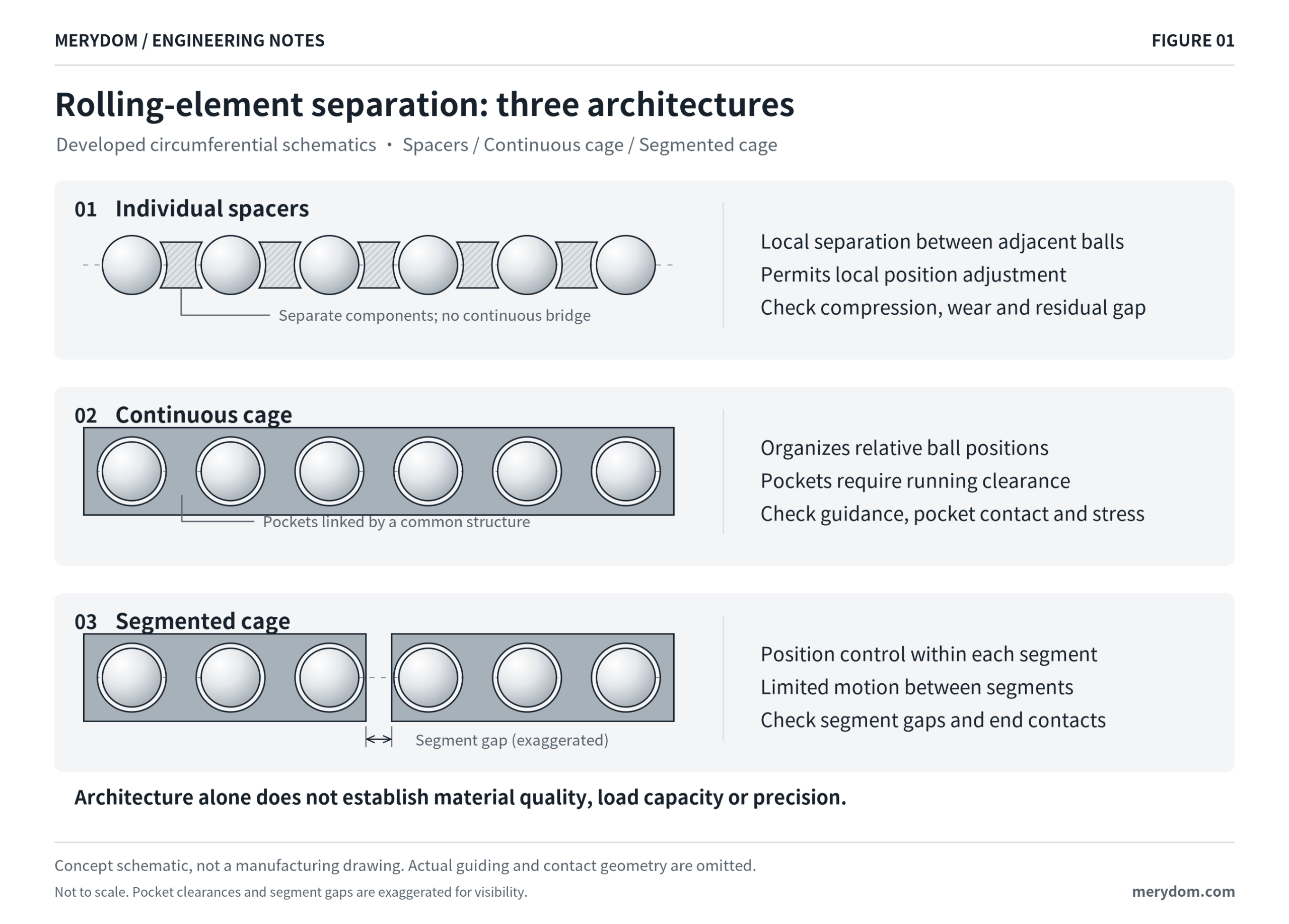
Figure 1. Three rolling-element separation architectures. Concept schematic only; not a manufacturing drawing.
The key point is:
Individual spacers provide mainly local constraint. A continuous cage provides stronger system-level position control. A segmented cage is an intermediate architecture.
This difference drives most of the mechanical behavior discussed below.
2. Spacer or Cage Is Not the Same Question as Polymer or Metal
A common misunderstanding is to compare "nylon spacers" with "metal cages" as though these were fixed design categories.
They are not.
The architecture and the material should be evaluated separately.
Possible separator or cage materials include:
- polyamide and other engineering polymers;
- PEEK and other high-performance polymers;
- steel;
- brass or bronze alloys;
- other application-specific materials.
A polymer cage can be a continuous cage. A metallic component can also be used as an individual separator.
Material selection should therefore consider:
- operating temperature;
- lubricant and additive compatibility;
- dimensional stability;
- long-term compression or creep;
- wear behavior;
- corrosion;
- mass and inertia;
- manufacturing method;
- cost;
- inspection and traceability requirements.
The name of the material alone does not establish the performance of the bearing.
3. Why Are Rolling Elements Separated at All?
Rolling elements are designed to roll on the raceways, but direct contact between neighboring rolling elements is not pure rolling.
When two balls contact each other, their surface velocities at the contact can create sliding. Direct rolling-element contact can therefore generate additional:
- friction;
- heat;
- wear;
- surface damage;
- instability.
A spacer or cage replaces uncontrolled ball-to-ball contact with a designed interface.
However, this does not eliminate friction.
The rolling elements still interact with:
- spacer surfaces;
- cage pockets;
- cage guiding surfaces;
- lubricant;
- seals;
- raceways.
The correct engineering question is therefore not:
"Which system has no friction?"
It is:
Which system keeps contact pressure, relative sliding, heat generation and lubrication behavior within acceptable limits under the intended duty cycle?
4. The Main Advantage of Individual Spacers: Local Freedom
Large slewing bearings are structurally different from small rigid bearing cartridges.
Because their diameter is large relative to ring cross-section, the rings can deform significantly under:
- axial load;
- radial load;
- overturning moment;
- bolt preload;
- flange deformation;
- local support flexibility;
- manufacturing variation.
A spacer system does not mechanically connect the entire rolling-element set through a continuous ring. This can provide useful local accommodation when different circumferential zones move differently.
That does not mean each spacer is mechanically isolated.
If the rolling elements and spacers are all in contact, compressive forces can be transmitted through the sequence. A local reduction in available circumferential space can still create:
- spacer compression;
- increased contact pressure;
- abnormal sliding;
- local heating;
- indentation;
- wear;
- possible jamming.
Therefore, the benefit of local freedom must always be considered together with the available circumferential residual gap.
5. Circumferential Residual Gap: A Critical but Often Misunderstood Parameter
When balls and individual spacers are assembled around a slewing bearing raceway, their combined circumferential length will not normally fill the circumference with zero remaining space.
The remaining free space in the rolling-element set can be described as a circumferential residual gap.
For the distinction between ring movement and internal free space, see our slewing bearing clearance and wear measurement guide.
This is fundamentally different from:
- radial bearing clearance;
- axial bearing clearance;
- cage pocket clearance;
- raceway hardening gap.
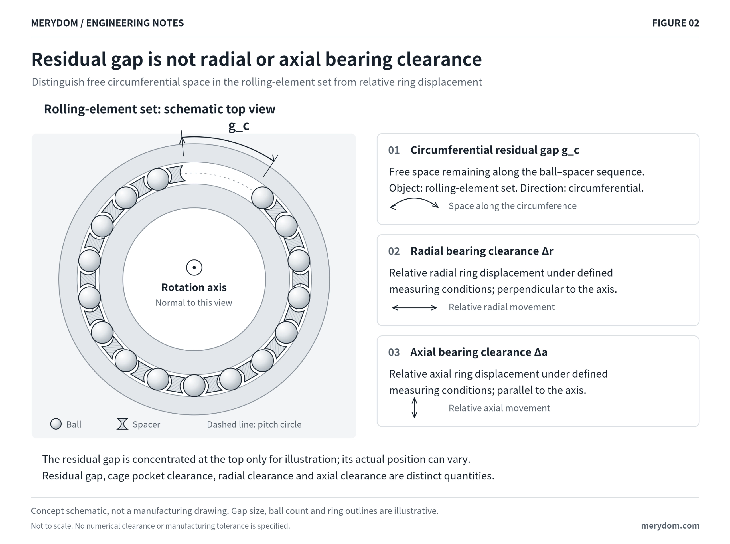
Figure 2. Circumferential residual gap is free space in the rolling-element/spacer sequence; it is not radial or axial bearing clearance.
In a large-diameter bearing, the accumulated residual gap can become significant in absolute length even when each dimensional contribution is small.
This has several implications.
The residual gap can move
Because the spacers are independent, the free circumferential space does not have to remain at one fixed location.
Its position can change with:
- rotation;
- gravity;
- load distribution;
- acceleration and deceleration;
- ring deformation;
- friction.
Orientation can matter
For a bearing whose rotation axis is vertical, gravity does not act around the circumference in the same way as it does when the bearing plane is vertical and the rotation axis is horizontal.
In a vertical bearing plane, gravity can influence the circumferential distribution of a freely spaced rolling-element set. That does not mean every vertically installed bearing must use a cage, but orientation should be included in the design review.
"Fill it as tightly as possible" is not a general design rule
The residual gap must be considered as part of a dimensional system that also changes with:
- manufacturing tolerances;
- thermal expansion;
- moisture conditioning of some polymers;
- ring deformation;
- assembly conditions.
Removing too much circumferential freedom can create compression or jamming risks.
6. Why Individual Spacers Are Common in Heavy, Slow Slewing Applications
Many construction and material-handling slewing bearings operate under conditions such as:
- low rotational speed;
- intermittent rotation;
- frequent starts and stops;
- reversing motion;
- high axial load;
- high overturning moment;
- relatively limited continuous high-speed operation.
Typical applications include:
- excavators;
- mobile cranes;
- truck cranes;
- aerial work platforms;
- material handlers;
- industrial turntables.
In these applications, a well-designed spacer system can provide several practical advantages:
- simple internal architecture;
- compact packaging;
- local accommodation of circumferential motion;
- established manufacturing experience;
- potentially high rolling-element complement;
- competitive cost.
This is why the presence of individual spacers should not be interpreted as a low-grade design.
For many applications, it is an appropriate engineering solution when the operating conditions and internal clearances have been verified.
7. Why Continuous Rotation Often Favors a Cage
A cage becomes more attractive when the application benefits from more controlled circumferential organization of the rolling elements.
Typical factors include:
- continuous 360-degree rotation;
- increasing rotational or circumferential speed;
- strong requirements for repeatable running behavior;
- concern about rolling-element redistribution;
- installation orientation that makes free circumferential redistribution less desirable.
A cage maintains a more regular relationship between rolling-element positions.
This can reduce one source of variability: uncontrolled circumferential redistribution of the rolling elements.
However, this point must be stated carefully.
A cage does not make all rolling-element loads equal
Even with perfect angular spacing, the bearing still has load zones.
Under radial load or overturning moment, balls at different circumferential positions naturally carry different loads. Support flexibility, raceway geometry, manufacturing error and preload also affect the load distribution.
Therefore:
A cage controls rolling-element position; it does not eliminate the physical load distribution created by the application.
8. The Cage Itself Becomes a Loaded Mechanical Component
This is one of the most important differences between a continuous cage and independent spacers.
The rolling elements in a large four-point contact bearing do not all experience exactly the same instantaneous motion.
Their local motion can vary because of differences in:
- normal load;
- contact angle;
- raceway traction;
- ring deformation;
- elastic deflection;
- multi-point contact state;
- acceleration and reversal.
The cage, however, links multiple rolling elements.
If a ball moves relative to its nominal pocket position and consumes the pocket clearance, it contacts the cage pocket.
The cage may then experience:
- pocket impact;
- sliding;
- compression;
- tension;
- bending;
- local stress;
- wear;
- dynamic instability.
Research on wind-turbine blade bearing cage loads has specifically examined rolling-element-to-cage contact and cage loads in very large four-point contact ball bearings. This is important because it shows that low rotational speed does not automatically mean low cage stress.
The bearing may rotate slowly while still experiencing significant cage loading because of:
- large structural deformation;
- oscillating motion;
- high external loads;
- rolling-element differential motion.
Therefore:
A cage should not simply be made "as stiff as possible." It must combine sufficient strength with appropriate pocket clearance, guidance and deformation compatibility.
9. RPM Alone Is Not a Sufficient Selection Criterion
A universal rule such as "above X rpm use a cage" is not technically robust for slewing bearings.
Diameter matters.
A useful reference quantity is the circumferential speed at the rolling-element pitch diameter:
v_ref = π × D_p × n / 60
where:
D_p= rolling-element pitch diameter in metres;n= relative rotational speed in revolutions per minute;v_ref= reference circumferential speed in metres per second.
For example, at the same speed of 5 rpm:
- a 0.2 m pitch diameter gives approximately 0.052 m/s;
- a 2.0 m pitch diameter gives approximately 0.524 m/s.
The second bearing has ten times the reference circumferential speed even though both are rotating at 5 rpm.
This value is not identical to ball orbital speed or local sliding velocity at the spacer or cage contact. It is simply a useful reminder that bearing size must be considered together with rpm.
A proper review should include:
- rpm;
- pitch diameter;
- continuous versus intermittent motion;
- acceleration;
- deceleration;
- reversals;
- dwell time;
- oscillation angle;
- temperature.
10. A Cage Does Not Automatically Mean Lower Friction Torque
Slewing-bearing torque is a system-level result.
It can be affected by:
- preload;
- internal clearance;
- preload scatter;
- raceway geometry;
- conformity;
- contact angle;
- ring deformation;
- mounting structure stiffness;
- seals;
- lubricant;
- contamination;
- rolling-element separation architecture.
Therefore, a higher measured starting torque should not automatically be blamed on spacers, and a cage should not be specified merely on the assumption that it will always reduce torque.
For applications sensitive to torque consistency, a more defensible specification is to define:
- maximum starting torque;
- running torque;
- reversal torque;
- torque fluctuation;
- test load;
- temperature;
- lubrication condition;
- mounting condition;
- test speed.
Then compare candidate designs under the same test conditions. Define the required records using the slewing bearing inspection report guide.
Torque consistency is not the same as positioning accuracy
Positioning accuracy is also influenced by:
- bearing runout;
- tilting stiffness;
- backlash in the drive;
- gear accuracy;
- structural deflection;
- control system;
- mounting accuracy.
A cage can improve rolling-element positional organization, but "caged bearing" should never be used as a substitute for a defined precision requirement.
11. Lubrication Can Be More Important Than the Separator Architecture
A large amount of grease inside the bearing does not necessarily mean that the rolling contact is adequately supplied.
This is especially important in:
- small-angle oscillation;
- long dwell periods;
- frequent reversals;
- heavily loaded contact zones.
Research on grease-lubricated oscillating bearings has shown that starvation and re-lubrication depend on the motion and grease behavior around the contact inlet.
For slewing-bearing design, the lubrication review should therefore consider:
- oscillation amplitude;
- rotation direction changes;
- grease entry points;
- grease distribution around the circumference;
- re-lubrication interval;
- grease consistency;
- base oil;
- additive package;
- temperature;
- contamination;
- separator geometry.
Spacer or cage geometry may influence how grease is distributed locally, but changing the separator architecture is not a substitute for correcting a lubrication problem. Our slewing bearing lubrication guide explains the related maintenance considerations.
12. Material Selection: What Should Be Evaluated?
The separator material must be evaluated as part of the operating system.
| Material family | Potential reasons to consider it | Key checks |
|---|---|---|
| Engineering polymers such as polyamide | Low mass, useful sliding behavior, flexible manufacturing | Exact grade, conditioning, dimensional stability, creep, temperature and lubricant compatibility |
| High-performance polymers such as PEEK | Candidate for more demanding temperature or chemical environments | Exact formulation, contact pressure, wear, temperature, chemical compatibility and cost |
| Steel | Strength and structural design flexibility | Surface interaction, lubrication, wear, corrosion and fatigue |
| Brass or bronze alloys | Application-specific tribological and mechanical properties | Exact alloy, mass, wear, lubrication compatibility and cost |
This table is not a ranking.
A high-temperature cage material does not automatically establish the temperature rating of the complete bearing. Seals, grease, raceway treatment and other components may have lower limits.
Similarly, specifying only "nylon spacer" is often insufficient for a demanding project.
Where internal separator performance is critical, the technical specification should identify:
- material grade;
- dimensional requirements;
- conditioning state if relevant;
- inspection method;
- traceability;
- allowed material substitutions.
13. Segmented Cages: An Important Intermediate Solution
The choice is not always limited to:
individual spacers versus one continuous cage.
A segmented cage can provide an intermediate approach.
Within each segment:
- rolling-element spacing is controlled;
- pocket geometry can guide the rolling elements.
Between segments:
- limited relative circumferential motion is possible.
Depending on segment guidance and end contact, this can shorten the structural load path and may reduce the tensile or compressive loads that would otherwise accumulate around a long continuous cage.
However, segmentation introduces its own design questions:
- How large is the segment gap?
- Can segment ends contact?
- What happens during reversal?
- How do temperature and tolerance accumulation change the gaps?
- How is each segment guided?
- Can a segment skew or jam?
A segmented cage is therefore not a compromise that automatically eliminates the disadvantages of both systems. It is a distinct architecture that requires its own verification.
14. Crossed-Roller Slewing Bearings Require Separate Consideration
The spacer-versus-cage discussion is different for crossed-roller bearings.
A ball mainly needs to be separated and guided through its contact geometry.
A roller additionally has an orientation that can become unstable.
Important issues include:
- roller skew;
- end contact;
- effective roller contact length;
- separator geometry;
- pocket geometry;
- guidance.
Crossed-roller bearing manufacturers use specialized spacer retainers specifically to control roller orientation while separating adjacent rollers.
This provides an important engineering lesson:
An individual separation element does not automatically mean low precision, and a continuous cage does not automatically mean higher load capacity.
The actual guiding geometry must be evaluated. For the wider bearing selection process, see the crossed-roller slewing bearing selection guide.
15. A Practical Engineering Selection Framework
Instead of asking only "spacer or cage?", start with the operating conditions.

Figure 3. Application-led selection workflow. The architecture should be validated against the duty cycle rather than selected from a universal rpm threshold.
Step 1 — Define the operating conditions
Collect at least:
- axial load;
- radial load;
- overturning moment;
- speed;
- pitch diameter;
- continuous rotation or oscillation;
- oscillation angle;
- start/stop frequency;
- reversal frequency;
- acceleration and deceleration;
- bearing orientation;
- operating temperature;
- duty cycle;
- maintenance interval.
Step 2 — Define shared constraints and acceptance criteria
Before comparing architectures, define the same engineering targets for all candidates:
- support stiffness;
- expected ring deformation;
- preload or clearance;
- starting torque;
- running torque;
- torque fluctuation;
- acceptable wear;
- temperature rise;
- lubrication requirements;
- contamination exposure;
- required service life;
- failure consequences.
Step 3 — Compare the architectures
Individual spacers should be considered when:
- duty is slow and intermittent;
- local accommodation is useful;
- the application has a proven spacer-bearing history;
- compact internal packaging is valuable;
- cost and simplicity are important.
Key checks:
- circumferential residual gap;
- spacer compression;
- contact pressure;
- wear;
- lubricant access;
- material stability.
A continuous cage should be considered when:
- continuous rotation is important;
- circumferential speed is increasing;
- controlled rolling-element spacing is important;
- redistribution of freely spaced rolling elements is undesirable;
- repeatable running behavior is a major design target.
Key checks:
- cage guidance;
- pocket clearance;
- pocket impact;
- structural stress;
- wear;
- temperature;
- lubrication.
A segmented cage should be considered when:
- rolling-element organization is required;
- a full continuous cage would experience excessive structural interaction;
- some circumferential freedom between sections is desirable.
Key checks:
- segment gaps;
- segment-end contact;
- reversal behavior;
- segment guidance;
- cumulative tolerances.
Step 4 — Reassess geometry, material and lubrication
Changing the separator architecture can change:
- rolling-element count;
- available internal space;
- cage or spacer thickness;
- lubricant distribution;
- thermal behavior;
- assembly procedure.
Therefore, do not assume that changing from spacers to a cage leaves the bearing’s internal geometry and load-carrying behavior unchanged.
Step 5 — Validate representative operating conditions
A useful validation program can include:
- torque-versus-angle measurement;
- starting and reversal torque;
- temperature rise;
- continuous running where relevant;
- oscillation testing;
- inspection after endurance testing.
After testing, inspect for:
- spacer indentation;
- spacer wear;
- pocket wear;
- cage bridge cracking;
- guiding-surface wear;
- segment-end damage;
- lubricant condition;
- abnormal contact patterns.
Smooth unloaded hand rotation is not sufficient validation for a highly loaded slewing-bearing application.
16. Selection Matrix
The following table is intended as a screening guide, not a universal rule.
| Operating characteristic | Individual spacers | Continuous cage | Segmented cage |
|---|---|---|---|
| Slow, intermittent slewing | Strong candidate | Possible | Possible |
| Continuous rotation | Conditional | Candidate for evaluation | Candidate; segment guidance and dynamics require review |
| Increasing circumferential speed | Requires careful review | Candidate for evaluation | Requires dedicated dynamic and guidance review |
| Frequent reversals | Common in many applications | Requires pocket/contact review | Requires segment-end review |
| High ring deformation | Local freedom can be useful | Cage loads must be checked | Can provide intermediate freedom |
| Strict rolling-element spacing control | Limited | Strong | Strong within each segment |
| Circumferential residual gap | Must be managed | Different constraint system | Segment gaps must be managed |
| Simple architecture | Strong advantage | More complex | More complex |
| Potential full-circumference cage stress | Not applicable as one continuous structure | Must be evaluated | Reduced load path, but not eliminated |
| Special temperature/chemical environment | Material-dependent | Material-dependent | Material-dependent |
| Crossed-roller guidance | Design-specific | Design-specific | Design-specific |
17. Questions Procurement and Engineering Teams Should Ask Suppliers
When two quotations use different separator systems, the following questions are more useful than simply asking which option is "better."
1. Does changing the cage or spacer system change the number of load-carrying rolling elements?
If yes, the load rating and internal geometry may need to be reassessed.
2. What separator or cage material grade is used?
Ask for the actual material specification, not only "nylon," "plastic," "steel" or "brass."
3. How is the circumferential tolerance system controlled?
For spacer designs, ask how residual gap is defined and verified.
4. How is the cage guided?
For caged designs, determine whether guidance is controlled primarily by rolling elements, a ring surface or another feature.
5. What are the verified operating limits?
Ask about:
- speed;
- temperature;
- duty cycle;
- load;
- lubrication;
- orientation;
- maintenance.
6. What torque values are guaranteed, and under what test conditions?
A torque number without load, temperature, lubrication and mounting conditions is difficult to compare.
7. Has the proposed architecture been validated in a similar duty cycle?
Application history is especially valuable for large slewing bearings because support deformation and machine-level behavior can dominate internal dynamics.
18. Common Misconceptions
Misconception 1: "A cage is always more advanced."
Not correct.
A cage provides stronger rolling-element position control, but it also introduces cage guidance, pocket contacts and structural loads.
Misconception 2: "Spacers are only for cheap bearings."
Not correct.
Individual spacers are widely used in large, heavily loaded slewing bearings where their simplicity and local freedom are useful.
Misconception 3: "Low speed means the cage is lightly loaded."
Not necessarily.
Large oscillating bearings can generate significant rolling-element-to-cage interactions even at low rotational speed.
Misconception 4: "A cage guarantees lower torque."
Not necessarily.
Torque depends on preload, raceway geometry, mounting deformation, seals, lubrication and internal interactions.
Misconception 5: "More rolling elements always mean higher real-world performance."
Not automatically.
Rolling-element count is only one part of capacity. Raceway geometry, material, hardness, structural deformation, load distribution and mounting all matter.
Misconception 6: "If a separator fails, use a stronger material."
Not always.
The root cause may be incorrect clearance, circumferential compression, differential motion, lubrication, contamination, temperature or structural deformation.
19. The Most Useful Way to Think About the Choice
The spacer-versus-cage decision can be understood as a trade-off between two engineering objectives.
Individual spacers emphasize local adaptability
They allow the rolling-element set to accommodate local circumferential motion without a single continuous structural link.
Continuous cages emphasize global positional organization
They maintain a more controlled relationship between multiple rolling elements but must accommodate differences in rolling-element motion through cage clearance, elasticity and guidance.
Segmented cages attempt to combine both ideas
They control positions within each section while allowing limited movement between sections.
This leads to the central conclusion:
The best separator architecture is the one that provides enough control to prevent harmful rolling-element interaction, while preserving enough freedom to accommodate the real deformation and motion of the bearing system.
Conclusion
There is no technically defensible universal rule stating that all low-speed slewing bearings should use spacers or that all higher-performance slewing bearings should use cages.
A reliable selection process should follow this sequence:
Define the actual motion and loads → assess mounting stiffness and ring deformation → define torque, wear and temperature requirements → review lubrication and material compatibility → compare spacer, continuous-cage and segmented-cage architectures → validate the selected design under representative operating conditions.
For procurement teams, the most valuable deliverable is not the name of the separator system. It is a documented operating envelope and evidence that the proposed design has been verified for that envelope.
For design engineers, the decisive question is:
Can the selected separation system prevent harmful contact while accommodating the rolling-element motion differences that will occur throughout the intended service life?
For a slewing-bearing application review, MERYDOM recommends providing the axial load, radial load, overturning moment, speed or oscillation profile, bearing orientation, operating temperature, lubrication conditions, support structure information and torque requirements. These inputs make it possible to discuss the internal architecture on the basis of the actual machine rather than external bearing dimensions alone.
Before requesting a quotation, use our RFQ engineering package guide to organize these inputs.
References
- thyssenkrupp rothe erde. "Inside the bearing: The difference between cages and spacers."
https://www.thyssenkrupp-rotheerde.com/en/newsroom/stories/inside-the-bearing-the-difference-between-cages-and-spacers - Kaydon Bearings. Slewing Ring Bearings Catalog 390.
https://www.kaydonbearings.com/downloads/catalog390/Kaydon_Catalog_390.pdf - Silverthin. "Slewing Ring Bearing Engineering: Components."
https://www.silverthin.com/engineering/slewing-ring-bearings/components/ - Silverthin. Thin Section and Slewing Ring Bearing Catalog.
https://www.silverthin.com/wp-content/uploads/2025/02/SilverThin-Thin-Section-and-Slewing-Ring-Catalog.pdf - Buescher, M., et al. "Cage Loads of Wind Turbine Blade Bearing." Journal of Physics: Conference Series, 1618 (2020), 052061.
https://doi.org/10.1088/1742-6596/1618/5/052061 - Li, Y., et al. "Dynamic Performance Analysis of Cage in Four-Point Contact Ball Bearing." Lubricants, 10(7), 149 (2022).
https://doi.org/10.3390/lubricants10070149 - Su, Y., Zhang, J., and Zhang, W. "Theoretical and experimental approaches for flexible cage dynamic characteristics of four-point contact ball bearing considering multi-point contact behaviors." Mechanical Systems and Signal Processing, 223, 111929 (2025).
https://doi.org/10.1016/j.ymssp.2024.111929 - Escanciano, I., et al. "Methodology for the assessment of the friction torque of ball slewing bearings considering preload scatter." Friction, 12 (2024), 1838–1857.
https://doi.org/10.1007/s40544-024-0867-6 - Wandel, S., et al. "Starvation and relubrication mechanisms in grease lubricated oscillating bearings." Tribology International, 165 (2022), 107276.
https://doi.org/10.1016/j.triboint.2021.107276 - Wandel, S., et al. "Starvation and Re-lubrication in Oscillating Bearings: Influence of Grease Parameters." Tribology Letters (2022).
https://doi.org/10.1007/s11249-022-01655-7 - Kaydon Bearings. "Extend wind turbine life with pitch bearing upgrades."
https://www.kaydonbearings.com/white_papers_16.htm - THK. "Cross-Roller Ring: Structure and Features."
https://www.thk.com/us/en/products/cross_roller_ring/cross_roller_ring/ - Stammler, M., et al. Wind Turbine Design Guideline DG03: Yaw and Pitch Bearings. NREL/TP-5000-89161 (2024).
https://www.nrel.gov/docs/fy24osti/89161.pdf
Technical Scope and Limitations
- Figures are conceptual schematics and are not manufacturing drawings.
- No universal speed threshold is implied by this article.
- Separator selection must be reviewed together with bearing geometry, preload or clearance, support stiffness, lubrication and operating duty cycle.
- Performance data from academic studies on one bearing size or application should not be transferred directly to another slewing-bearing design without engineering verification.