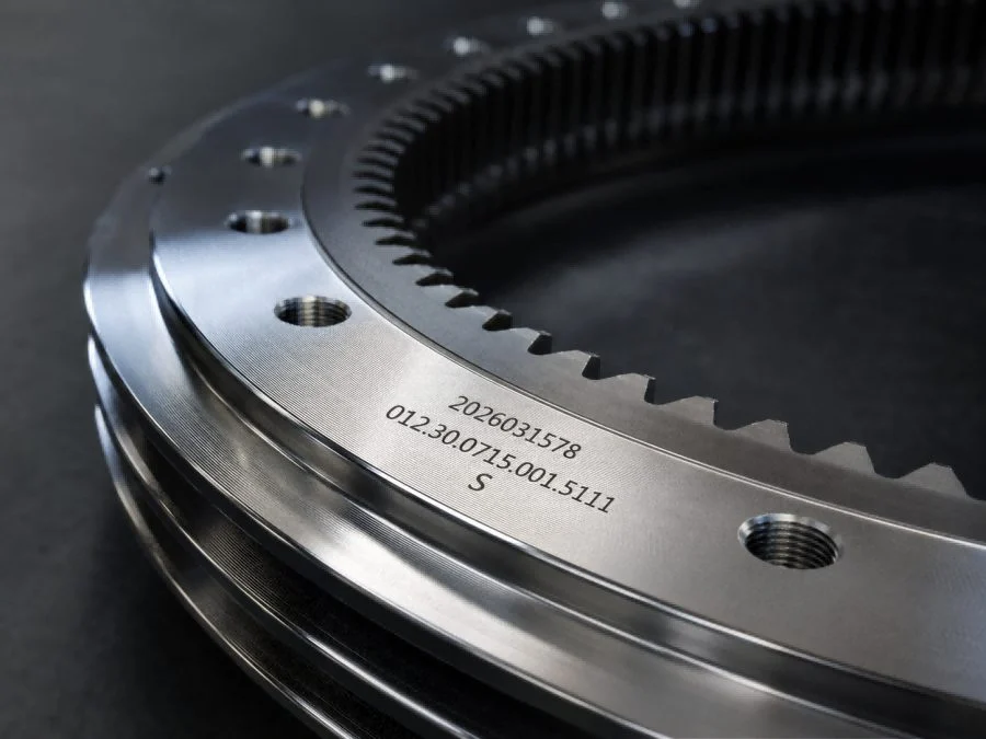
Verify replacement slewing bearing interchangeability through load capacity, raceway design, gearing, bolts, clearances, materials, sealing and installation.
Two slewing bearings can share outside diameter, bore and height yet differ in load capacity, internal geometry, gear tooth thickness, bolt-hole details, clearance, seals and hardness. Dimensional fit is necessary for replacement, but it is not proof of functional interchangeability.
A controlled second-source or replacement project compares the complete interface and duty. It also preserves uncertainty when original drawings or load cases are unavailable, so purchasing approval does not imply an engineering verification that was never performed.
Establish which document controls the replacement
Begin with the equipment manufacturer part number, bearing marking, approved drawing and revision. Record serial numbers and any suffix that may identify clearance, seals, accuracy or special material. If documents conflict with the removed bearing, stop and resolve whether the part was modified, repaired or previously substituted.
A used sample can provide dimensions and physical evidence, but wear, corrosion and deformation can change measurements. Distinguish measured values from nominal design values and record the instrument, position and uncertainty. Do not copy a damaged tooth or worn raceway condition into a new specification.
Compare the full mechanical envelope
Measure ring outside diameter, bore, total and individual ring heights, shoulders, pilots, chamfers and seal projections. Verify mounting-hole circles, quantities, diameters, thread form, counterbores and angular offsets. Confirm which ring rotates and the orientation of filling plugs, soft zones, grease ports and markings.
For internal gears, check available bore and pinion space; for external gears, check maximum tip diameter and guarding. Use the gear arrangement comparison when the proposed replacement changes the drive layout.
Verify gear compatibility with the existing pinion
Module and tooth count are only the beginning. Confirm pressure angle, profile shift, backlash allowance, face width, tooth-thickness measurement method, gear quality, material and hardness pattern. Inspect the existing pinion for wear, pitting and profile damage. A new ring paired with a worn pinion can create concentrated contact and rapid damage.
Calculate maximum tangential force from the machine torque spectrum and verify capacity. Check pinion adjustment range and mesh around the full bearing circumference after installation. Gear noise or smooth hand rotation alone cannot replace backlash and contact-pattern inspection.
Compare raceway design, capacity and operating condition
Confirm whether the bearing uses four-point balls, crossed rollers, double rows or three roller rows. Compare static limiting-load diagrams, fatigue method, internal clearance or preload, friction torque and permissible speed for the actual duty. Similar catalogue codes from different suppliers do not guarantee identical internal geometry.
When original load cases exist, repeat the selection check using the proposed bearing data. When they do not, state that only dimensional interchange has been verified and request equipment engineering approval. The load-case guide explains the data needed for a complete review.
- Raceway structure, rolling-element size and static limiting diagram.
- Clearance or preload class and rotation-torque expectation.
- Bolt assumptions, mounting stiffness and permitted flatness.
- Material, heat treatment, raceway and gear hardness.
- Seals, grease, corrosion protection and operating temperature.
- Inspection, serial traceability and first article evidence.
Control the first installation and approval
Use a documented first article or trial installation for a new source. Verify identification, dimensions, mounting contact, bolt process, backlash, lubrication, free rotation and baseline clearance. Preserve final records and photographs against the supplier and serial number.
Do not force a replacement into a distorted structure or use bolts to correct hole misalignment. Investigate any difference from the approved interface before commissioning. A successful physical installation is not complete until technical deviations and quality documents are closed.
FAQ
Are matching OD, ID and height enough for interchange?
No. Gear, holes, raceway capacity, clearance, materials, seals and mounting assumptions must also match the duty.
Can a used bearing be the only specification?
It is useful evidence, but wear and previous modifications mean it should not be the only design authority.
Should the existing pinion be inspected?
Yes. Wear or damage can prevent correct contact with the replacement gear ring.
Engineering references
For a drawing-based review, send MERYDOM the application, load cases, dimensions and required documentation. Final selection and service instructions must follow the approved drawing and equipment manufacturer requirements.